Mechanical Instructions
EN 7L04E AB 4.
4. Mechanical Instructions
Index of this chapter:
1. IBO Zapper Assy Removal
2. IBO Zapper Module Removal
3. IBO Zapper Panel Removal
4. Module Re-assembly
Notes:
• Only the digital module disassembly is described. For other
disassembly instructions, see the Service manual for
L04E AA 3122 785 14480.
• Figures below can deviate slightly from the actual situation,
due to different set executions.
• Make sure that both the ComPair connector and the UART
connector are shielded off with a piece of insulating tape
after repair for ESD reasons. Place this tape over the holes
in the rear cover of the set.
4.1 IBO Zapper Assy Removal
1. Remove the fixation screw.
2. Release the fixation clamp and pull the bracket backwards.
Figure 4-1 IBO Zapper bracket
4.2 IBO Zapper Module Removal
1. Disconnect all cables that lead to the module.
2. Unlock the clip at the left side of the bracket and pull out the
IBO Zapper module.
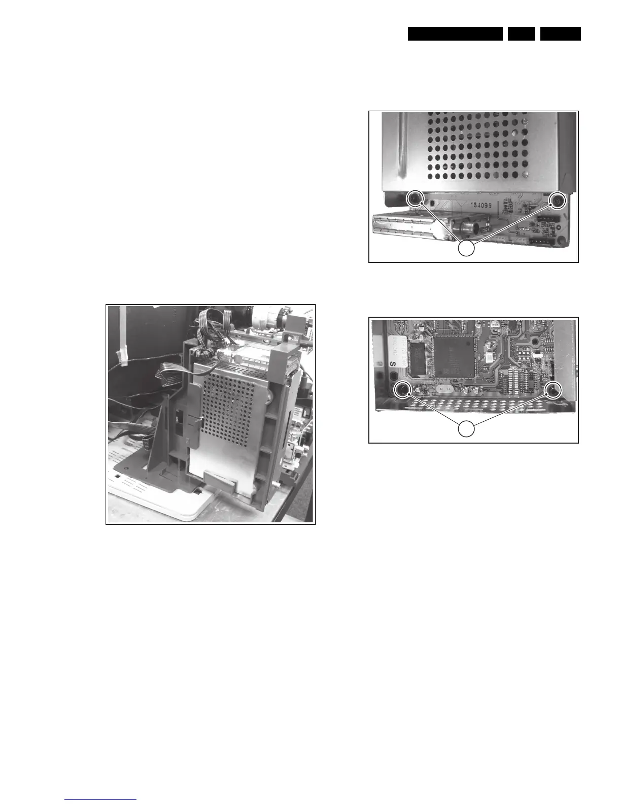
4.3 IBO Zapper Panel Removal
Figure 4-2 IBO Zapper Module Top Shield Removal
Figure 4-3 IBO Zapper Panel Removal
1. Unscrew the shield mounting screws [1] and lift the top
shield.
2. Unscrew the IBO Zapper panel mounting screws [2] and
take out the IBO Zapper panel.
4.4 Module Re-assembly
To re-assemble the whole module, do all processes in reverse
order.
E_14970_039.eps
090904
E_14970_037.eps
080904
1
E_14970_038.eps
080904
2