Alignments
EN 73L04E AB 8.
Enter the Service Alignment Mode (see also chapter 5 “Service
Modes, ....”). The SAM menu will now appear on the screen.
Select one of the following alignments:
• Options
• Tuner
• White Tone
• Geometry
• Audio
8.3.1 Options
Options are used to control the presence/absence of certain
features and hardware.
How to change an Option Byte
An Option Byte represents a number of different options.
Changing these bytes directly, makes it possible to set all
options very fast. All options are controlled via seven option
bytes. Select the option byte (OP1.. OP7) with the MENU UP/
DOWN keys, and enter the new value.
Leaving the OPTION submenu saves the changes in the
Option Byte settings. Some changes will only take effect after
the set has been switched “off” and “on” with the AC power
switch (cold start).
How to calculate the value of an Option Byte
• Calculate an Option Byte value (OP1 .. OP7) in the
following way:
• Check the status of the single option bits (OB): are they
enabled (1) or disabled (0).
• When an option bit is enabled (1) it represents a certain
value (see column “Bit value” in table below). When an
option bit is disabled, its value is 0.
• The total value of an Option Byte (decimal) is formed by the
sum of its eight option bits. The factory values are printed
on a sticker on the CRT.
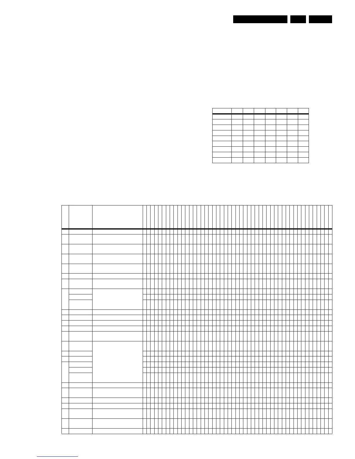
Table 8-1 Option Byte calculation
Option Bit Assignment
Following are the option bit assignments for all software
clusters.
Table 8-2 Option code overview per model
Bit (value) OP1 OP2 OP3 OP4 OP5 OP6 OP7
0 (1) OB10 OB20 OB30 OB40 OB50 OB60 OB70
1 (2) OB11 OB21 OB31 OB41 OB51 OB61 OB71
2 (4) OB12 OB22 OB32 OB42 OB52 OB62 OB72
3 (8) OB13 OB23 OB33 OB43 OB53 OB63 OB73
4 (16) OB14 OB24 OB34 OB44 OB54 OB64 OB74
5 (32) OB15 OB25 OB35 OB45 OB55 OB65 OB75
6 (64) OB16 OB26 OB36 OB46 OB56 OB66 OB76
7 (128) OB17 OB27 OB37 OB47 OB57 OB67 OB77
Total: Sum Sum Sum Sum Sum Sum Sum
Bit Byte_0 Description
21PT5458/01
21PT5509/01
21PT5518/01
21PT5518/05
21PT5518/58
21PT5618/01
21PT5618/05
21PT5618/58
25PT4458/01
25PT4458/05
28PT4458/01
28PT4458/05
28PT5008/01
28PT5008/05
28PT4408/01
28PT4418/01
29PT5408/01
29PT5408/58
29PT5458/01
29PT5509/01
29PT5518/01
29PT5518/05
29PT5518/58
29PT5618/01
29PT5618/05
29PT5618/58
24PW6518/01
24PW6518/05
28PW5408/01
28PW6008/01
28PW6008/05
28PW6008/58
28PW6408/01
28PW6408/05
28PW6408/58
28PW6508/01
28PW6518/01
28PW6518/05
28PW6518/58
28PW6558/01
28PW6618/01
28PW6618/05
28PW6618/58
32PW6408/01
32PW6408/05
32PW6518/01
32PW6518/05
32PW6618/01
32PW6618/05
7 MVK 0000000000000000000000000000000000000000000000000
6 OSVE Black current measuring in
overscan
0000000000000000000000000000000000000000000000000
5 TFR DC transfer ratio of luminance
signal
0000000000000000000000000000000000000000000000000
4 FSL Forced slicing level for vertical
sync
0000000000000000000000000000000000000000000000000
3 HP2 Synchronization of OSD/Text
display
0000000000000000000000000000000000000000000000000
2 HCO EHT tracking mode 1111111111111111111111111111111111111111111111111
1 FMI Connection of output of QSS
amplifier
0000000000000000000000000000000000000000000000000
0
QSS Mode of quasi split sound
amplifier
1111111111111111111111111111111111111111111111111
Decimal 5555555555555555555555555555555555555555555555555
Hex 0
5
0
5
0
5
0
5
0
5
0
5
0
5
0
5
0
5
0
5
0
5
0
5
0
5
0
5
0
5
0
5
0
5
0
5
0
5
0
5
0
5
0
5
0
5
0
5
0
5
0
5
0
5
0
5
0
5
0
5
0
5
0
5
0
5
0
5
0
5
0
5
0
5
0
5
0
5
0
5
0
5
0
5
0
5
0
5
0
5
0
5
0
5
0
5
0
5
Bit Byte_1 Description
7 SVMA Scavem On / Off 0000000000000000000000000000000000000000000000000
6 SAM Mode Service Align mode on/off 0000000000000000000000000000000000000000000000000
5 SDM Mode Service default mode on/off 0000000000000000000000000000000000000000000000000
4 White Pattern
On
Last colour pattern status in
factory mode
0000000000000000000000000000000000000000000000000
3 Continuous
Factory
Continuous factory mode
0000000000000000000000000000000000000000000000000
2 Reserved 0000000000000000000000000000000000000000000000000
1 Reserved 0000000000000000000000000000000000000000000000000
0
Reserved 0000000000000000000000000000000000000000000000000
Decimal 0000000000000000000000000000000000000000000000000
Hex 0
0
0
0
0
0
0
0
0
0
0
0
0
0
0
0
0
0
0
0
0
0
0
0
0
0
0
0
0
0
0
0
0
0
0
0
0
0
0
0
0
0
0
0
0
0
0
0
0
0
0
0
0
0
0
0
0
0
0
0
0
0
0
0
0
0
0
0
0
0
0
0
0
0
0
0
0
0
0
0
0
0
0
0
0
0
0
0
0
0
0
0
0
0
0
0
0
0
Bit Byte_2 Description
7 PSNS For PAL colour enhancement in
ES4
0000000000000000000000000000000000000000000000000
6 Factory Mode Factory mode on 0000000000000000000000000000000000000000000000000
5 Surf Mode Surf mode on/off 0000000000000000000000000000000000000000000000000
4 Child Lock
Mode
Child lock enabled 0000000000000000000000000000000000000000000000000
3Last Power
Mode
Last power status of the set 1111111111111111111111111111111111111111111111111
2 Cable Mode Cable/Antenna mode 0000000000000000000000000000000000000000000000000