OPERATION DESCRITPION
Data inputs
(DLEN, DATA)
The SAA1060
processes serially
the
18-bit data words synchronized with the
clock burst (CLB) and applied to
the data input DATA. A command will be accepted only when the data line
enable input (DLEN) is HIGH.
16^'^bit
1®^bit
load P
0 N
M L K J 1
H G
F E D C B A
bit
'^16
Qi5 Qi4
°13
Ol2
Oil ^10
°9
00
a
^7
Qe
Q
5
Q
4
Q
2
°1
leading
zero
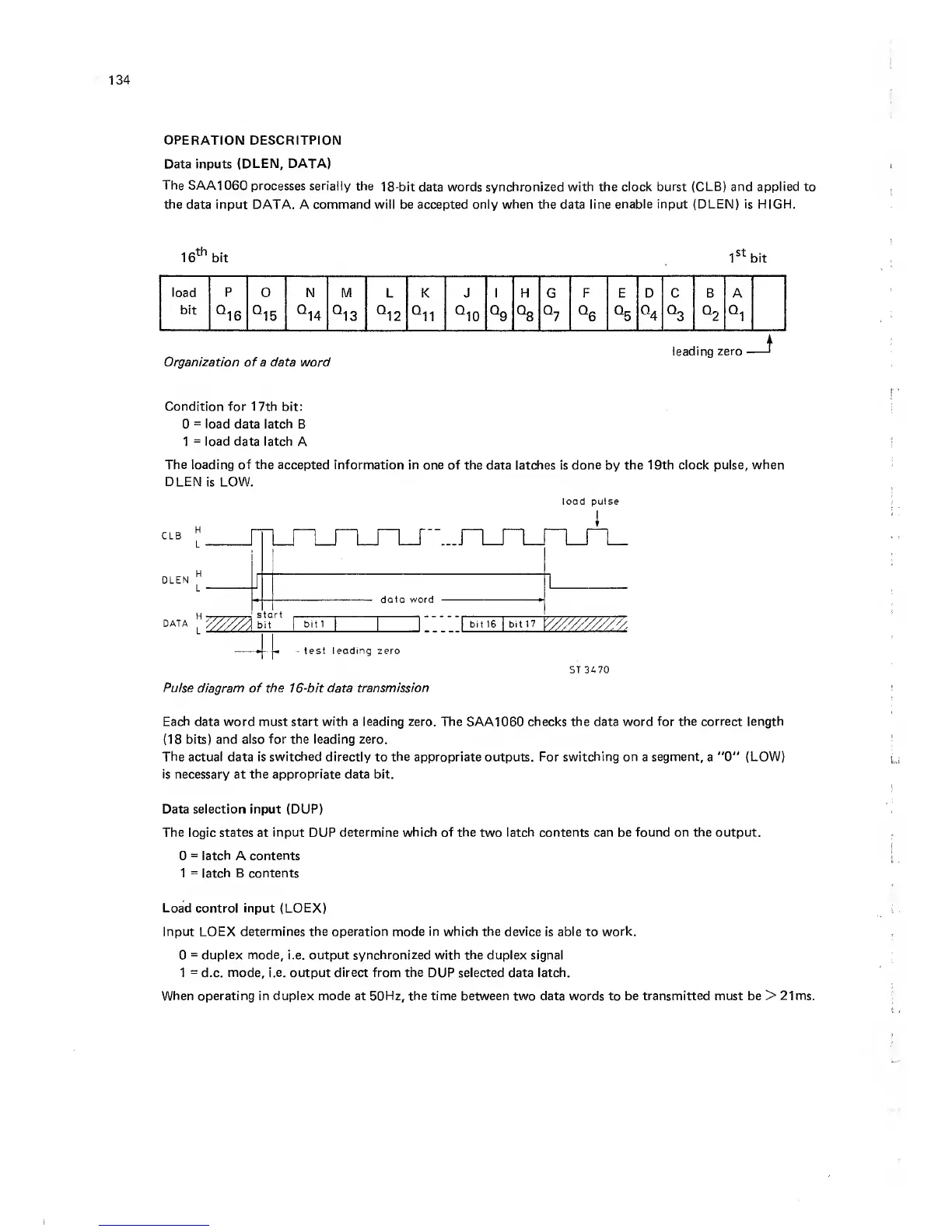
Organization of a data word
Condition for 17th
bit;
0
=
load
data latch B
1
=
load data latch
A
The loading of the accepted information
in one of the
data latches is
done
by
the 19th clock pulse,
when
DLEN
is LOW.
DLEN
^
L
data word
DATA
bit 1
-
test leading zero
Pulse diagram of the
16-bit
data transmission
load pulse
J LJ LJ
LJ L_
1
1
bit
16
I
blt17
'K^//'y///////z
ST 3470
Each
data word must start
with
a leading zero. The SAA1060 checks the data word
for the correct length
(18
bits) and also
for the leading zero.
The
actual data is
switched directly
to
the
appropriate outputs. For
switching on
a
segment,
a
"0"
(LOW)
is necessary at the appropriate data bit.
Data selection input (DUP)
The
logic
states
at
input DUP determine which of the
two
latch contents can be found on the output.
0
=
latch
A
contents
1
=
latch B contents
Load
control
input (LOEX)
Input LOEX determines the operation mode in which the device is able
to
work.
0
=
duplex mode,
i.e. output synchronized with the duplex signal
1
=
d.c.
mode, i.e.
output
direct
from
the
DUP selected data latch.
When operating in duplex mode at 50Hz, the time between two data words to be transmitted must be >
21 ms.