38
Protection for
the current source is
afforded
by
the PTC resistor R401
and
zener diodes V450,
V451
,
V452
and
diode-connected
transistor
V403.
In the event
of
a
high
voltage/current on the input terminals R401
goes
high
resistance. To
prevent part of
IRx
leaking through
the
protection diodes, the emitter of
V403
and the cathode
of zener
diode
V450
are
connected to Vx
and
the electrodes are routed back to the
-Vin input
of the compensation
amplifier.
The leakage
current through the diodes is
therefore balanced out in
the same way as
compensation is
achieved
for
the ADC
input
current.
1.
4.
2.
6.
Diode
measurements
Diode
measurements, and measurement of semiconddctor
junctions are
performed in the
same way
as
for
resistance
measurements in the 2kf2 range.
The value displayed
is the voltage
in forward or
reverse direction
across
the
diode
in
the
2V
range.
In
the diode measuring range, the constant current
derived from the
OQ0063
is 1mA
(see
previous section).
1.
4.2.7.
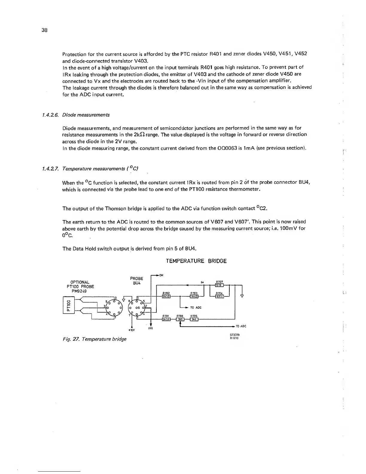
Temperature measurements (°C)
When the
°C
function is selected,
the constant current IRx
is routed from pin 2
of the
probe connector BU4,
which is
connected
via the probe lead to
one end of the PT100
resistance
thermometer.
The output of the
Thomson
bridge is
applied
to
the
ADC via
function switch
contact
°C2.
The earth
return to the ADC is routed to the
common sources of
V607
and
V607'.
This point is now
raised
above
earth
by
the potential drop across
the bridge caused
by
the measuring
current source;
i.e. lOOmV for
0°C.
The Data Hold
switch output is derived
from
pin 5
of
BU4.
TEMPERATURE BRIDGE
Fig.
27. Temperature bridge
ST3379
81 1210