37
1. 4.2.5.
Resistance measurements
(^j
The unknown
resistance connected
to
the BU2 input is fed via
the 12
1
function selector
switch contact to
the
voltage attenuator and is
supplied
with a constant current
IRx, via contact
122,
from the constant current
source A401 (OQ0063).
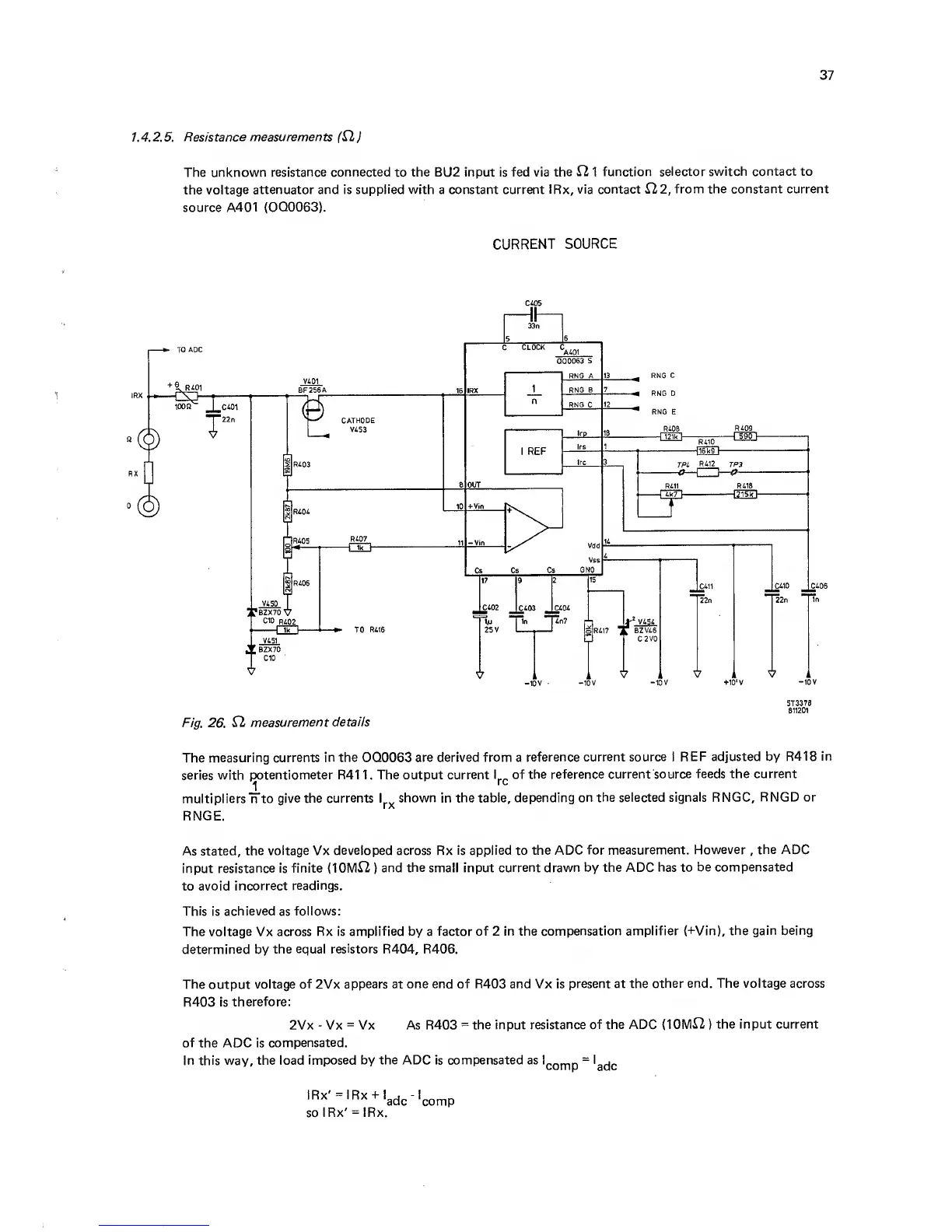
CURRENT
SOURCE
C405
Fig.
26.
12
measurement
details
ST3376
B11201
The measuring currents
in the
OQ0063
are derived from a
reference current
source I REF adjusted by R418
in
series with
potentiometer R41
1 .
The output
current I of the
reference current
source feeds the current
J.
multipliers
n to
give the currents I
shown
in
the table, depending
on the selected
signals
RNGC,
RNGD or
RNGE.
As stated,
the voltage Vx
developed
across Rx
is applied
to
the ADC
for measurement.
However
,
the ADC
input
resistance is finite (10IVI12
)
and
the
small input
current drawn by the ADC
has
to
be compensated
to avoid
incorrect
readings.
This
is
achieved
as
follows;
The
voltage
Vx
across Rx is
amplified
by a
factor of 2 in the
compensation amplifier (+Vin),
the gain being
determined
by
the
equal resistors
R404, R406.
The
output
voltage
of
2Vx
appears at one end of R403 and Vx is
present at the
other end. The voltage across
R403
is
therefore:
2Vx
-
Vx
=
Vx As R403
=
the input
resistance of the ADC (10M12
)
the input current
of
the ADC is
compensated.
In this
way,
the load
imposed by the ADC is compensated as