1-8-1 U29PCEUEA
ELECTRICAL ADJUSTMENT INSTRUCTIONS
General Note: "CBA" is an abbreviation for
"Circuit Board Assembly."
NOTE:
1.Electrical adjustments are required after replacing
circuit components and certain mechanical parts.
It is important to do these adjustments only after
all repairs and replacements have been com-
pleted. Also, do not attempt these adjustments
unless the proper equipment is available.
2.To perform these alignment / confirmation proce-
dures, make sure that the tracking control is set in
the center position: Press either "L5??" or "K" button
on the remote control unit first, then the "PLAY"
button (Front Panel only).
Test Equipment Required
1.Oscilloscope: Dual-trace with 10:1 probe,
V-Range: 0.001~50V/Div.,
F-Range: DC~AC-20MHz
2.Alignment Tape (9965 000 14514)
Head Switching Position Adjustment
Purpose:
To determine the Head Switching point during
playback.
Symptom of Misadjustment:
May cause Head Switching noise or vertical jitter
in the picture.
Reference Notes:
Playback the Alignment tape and adjust VR501 so that
the V-sync front edge of the CH1 video output wave-
form is at the 6.5H(412.7µs) delayed position from the
rising edge of the CH2 head switching pulse wave-
form.
Test point Adj.Point Mode Input
J23(V-OUT)
TP502(RF-SW)
GND
VR501
(Switching Point)
(MAIN CBA)
PLAY
(SP)
-----
Tape
Measurement
Equipment
Spec.
9965 000 14514 Oscilloscope
6.5H±1H
(412.7µs±60µs)
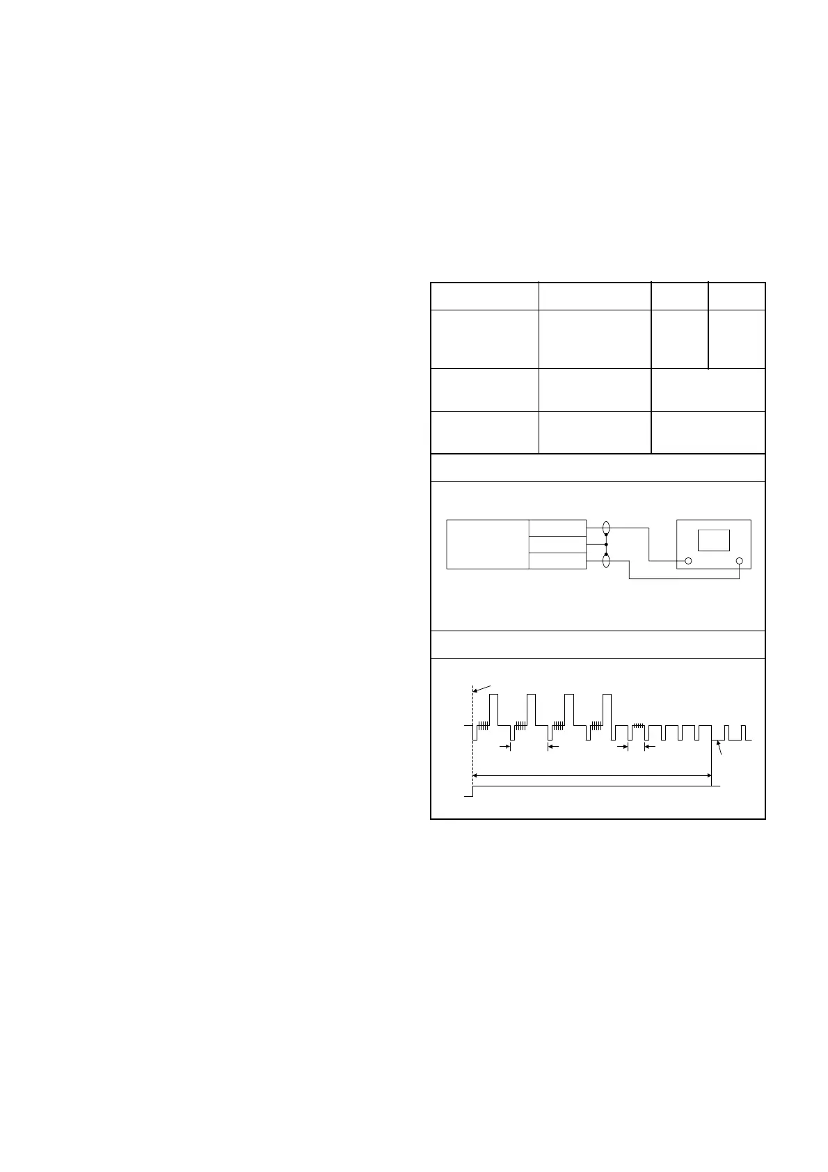
Connections of Measurement Equipment
Figure 1
Oscilloscope
Main CBA
J23
CH1 CH2
Trig. (+)
GND
TP502
EXT. Syncronize Trigger Point
CH1
CH2
1.0H
0.5H
V-Sync
Switching Pulse
6.5H±1H (412.7µs±60µs)