1-8-2 U29PCEUEA
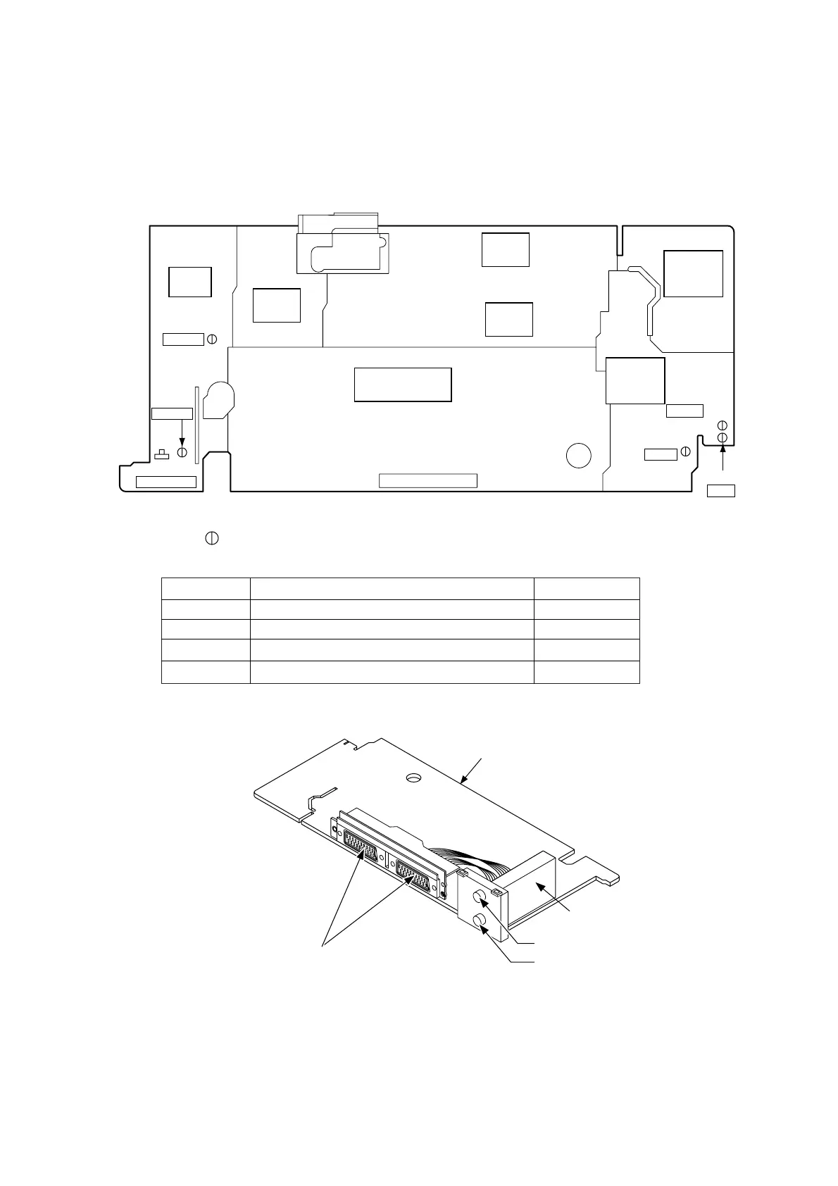
Adjustment Points and Test Points
TEST POINT INFORMATION
: Indicates a test point with a jumper wire across a hole in the PCB.
Main CBA Top View
Test Point
TP301
TP502
TP501
TP507
Used in: Page No.
Mechanical Alignment Procedures
Mechanical Alignment Procedures
Mechanical Alignment Procedures
Preparation for Servicing
2-3-3, 2-3-4
2-3-3, 2-3-4
2-3-3
1-4-1
TEST POINTS NOT USED IN ELECTRICAL ADJUSTMENTS
Main CBA
Tuner Unit
Antenna In
Audio In/Out,Video In/Out
Antenna Out
TP502
RF-SW
TP501
CTL
TP301
C-PB
VR501
SW-POINT
POWER
SUPPLY
BLOCK
POWER
CTL
BLOCK
VIDEO
BLOCK
Hi-Fi
BLOCK
SYSCON/TIMER
SERVO BLOCK
AUDIO
BLOCK
TUNER
BLOCK
J23
V-OUT
TP507
S-INH