www.phocos.com 9 | P a g e
Crimp one battery ring terminal (included) to each the positiveand negative battery lead (unit s ide). If choosing
r ing terminals other thanthe included ones, make s ure theyhave an inside ring diameter of 8.4 mm, 0.31 in
(PSW-H-5KW-120/48 V, PSW-H-6.5KW-120/48V and PSW-H-8KW-230/48V ) or 6.4mm, 0.25 in (all other models) to
fit the battery terminal bolts of the Any-Grid securely.
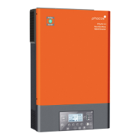
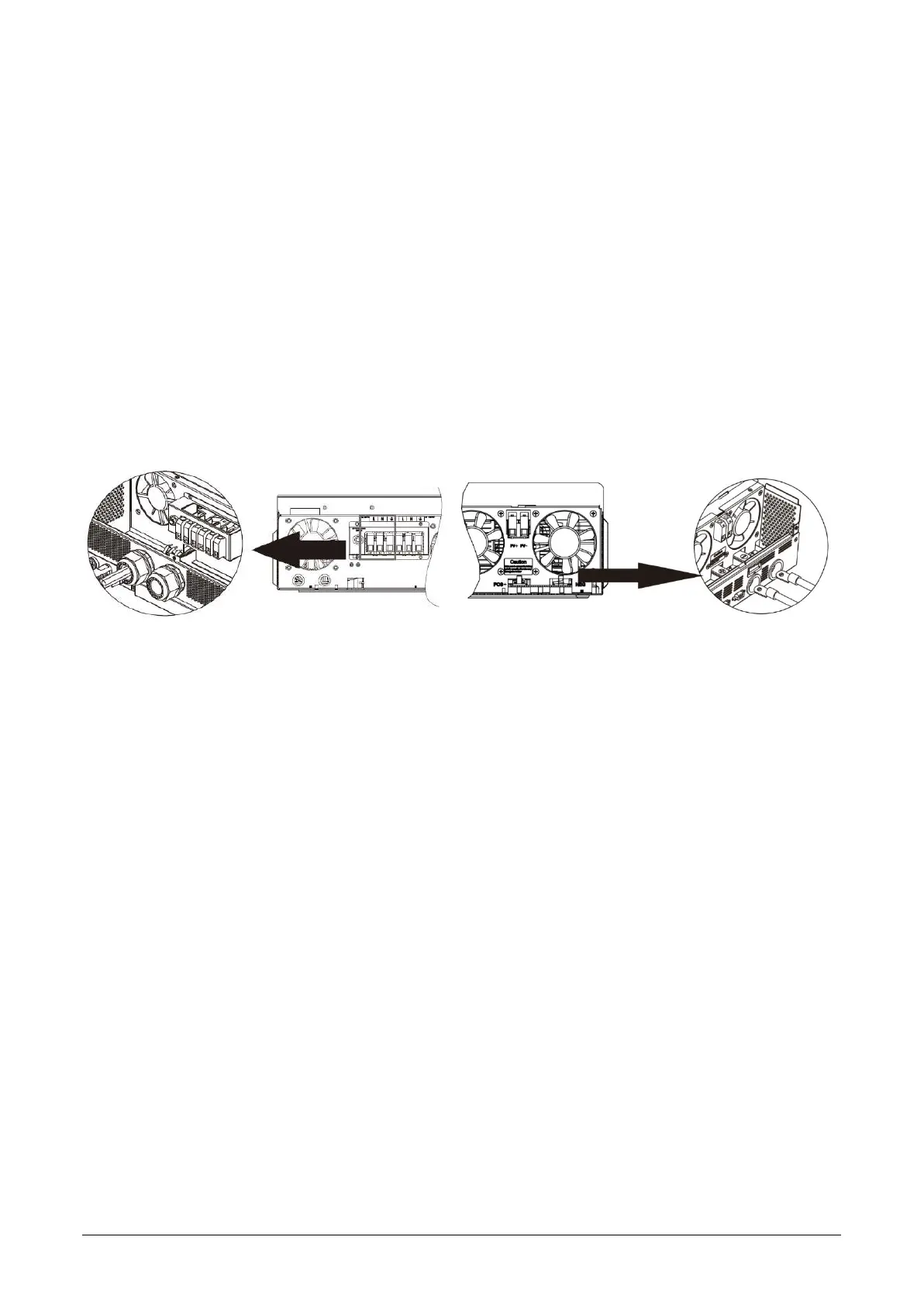
2. Remove the pre-installed nuts from the battery terminal bolts. Insert the ringterminal of the battery cables
through the casing holes (cable glands for 120 Vac models) and flat onto the corresponding battery terminal
(Fig. 6). Screw down the previously removed nut s with a torque of 5 Nm, 3.7 lbf-ft (PSW-H-5KW-120/48V, PSW-H-
6.5KW-120 /48V and PSW-H-8KW-230 /48V) or 2 ~ 3 Nm, 1.5 ~ 2.2 lbf⋅ft (all other models). Ensure the ring
terminals sit flush on the connectors.
CAUTION: Do not apply any antioxidant substances to the battery terminals of the unit before they are
adequately fastened.
CAUTION: Over-tightening the terminal nuts can cause damage to the terminal, under-tightening can
cause a loose connection and excessive heat during operation, make sure to use the prescribed torque.
3. Install the fuse holder or breaker in the pos itive battery cable (or negative, if the battery must be positive-
grounded).
WARNING: Ensure the fuse is not yet installed or make sure the circuit breaker is secured in the open
position for the rest of the installation procedure until instructed to do otherwise.
4. Connect the other end of the battery cables to theb attery. Ensure the polarity of the battery terminals onthe
Any-Grid match the battery polarity.
CAUTION: Reverse polarity connection to the battery may damage the unit.
PSW-H-5KW-120/48V, PSW-H-6.5KW-120/48V All other models
and PSW-H-8KW-230/48V
Fig. 6: Battery connection
5.5 AC Input and AC Output Connection
WARNING: Before connecting an AC source to the AC input of the Any-Grid, install an AC circuit breaker
between the Any-Grid and AC input power source. This will ensure the inverter can be securely disconnected
during maintenance and fully protected from over current of AC input. Make sure the breaker is open / off for
the rest of the installation procedure until instructed otherwise.
WARNING: Ensure that the installation has adequate grounding and connect the protective earth (PE)
terminals to this ground as instructed below. Failure to do so can cause serious injury or death once the unit is
powered up or the AC source is activated via its breaker.
WARNING: Ensure the AC cables are sized according to the table below. Inadequate AC cables can cause
excessive heat or fire during operation.
CAUTION: Do not connect an AC source to the “AC OUTPUT” labelled terminal of the unit as this will destroy
the unit. Only connect it to the “AC INPUT” labeled terminal.
CAUTION: Only AC sources with a neutral may be used. Using two phases on a single Any-Grid instead, will
cause damage.
CAUTION: Short-circuiting the L (live phase) AC input or AC output terminal to the metal body of the unit will
cause permanent damage not covered under warranty.
Recommended AC cable cross-section and AC circuit breakerrating:

 Loading...