www.phocos.com 8 | P a g e
• Ensure a minimum distance to other objects and surfacesas shown in
Fig. 5.1 to guarantee sufficient heat dissipation and to have enough space
for removing wires.
• Install in a room where noise is not an issue as the unit has
fans for cooling. Under maximum load, the fan noise
typically does not exceed 60 dBa.Under no load, but with
the AC output turned on, the minimum noise is
app roximately 35 dBa,as the fans rot ate at about30% of
their maximum speed.The fans are speed-controlled
according to current PV and inverter power. Air is taken in
from the top vents and expelled towardthe bottom.
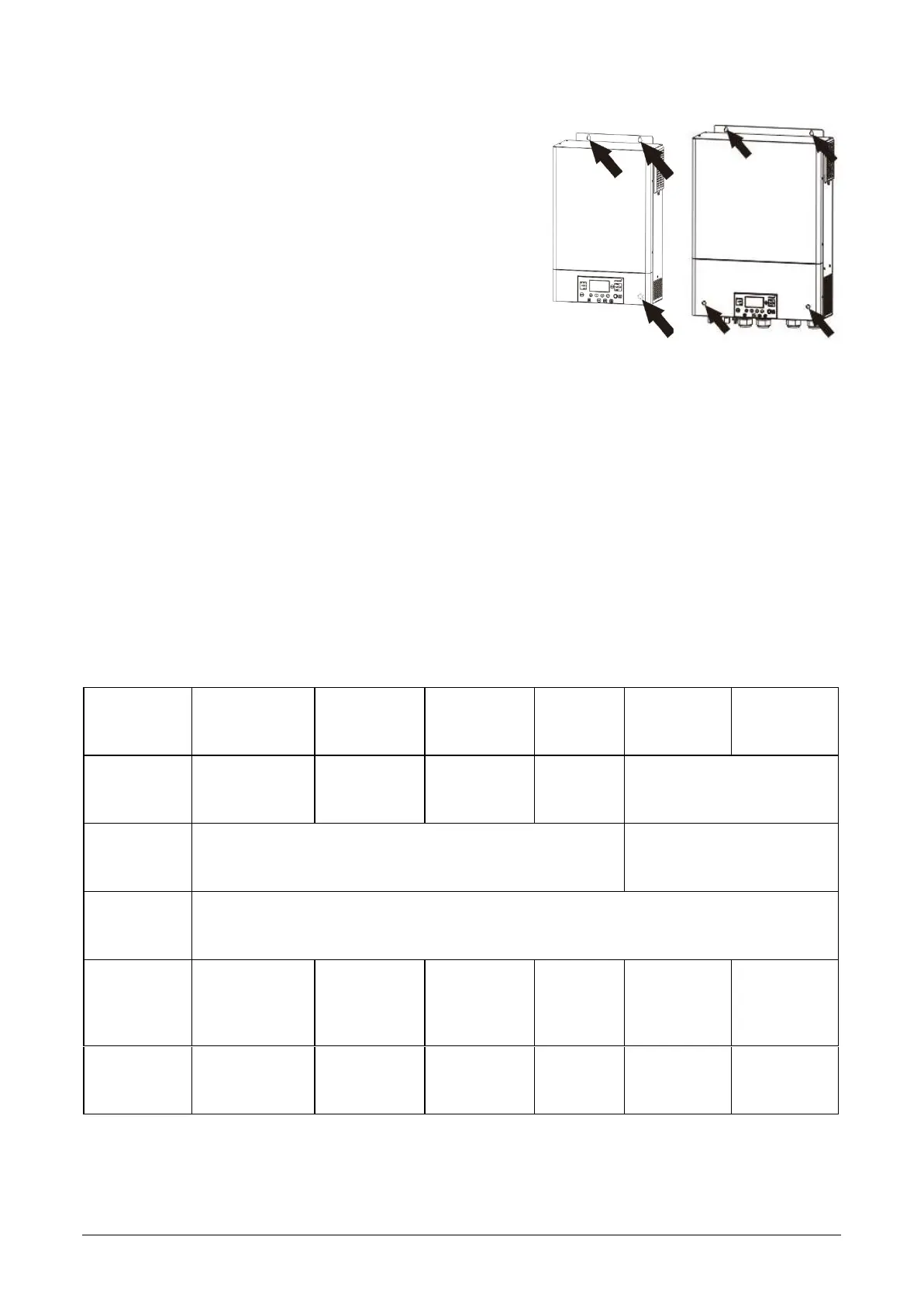
Install the unit by using four (PSW-H-5KW-120/48V, PSW-H-6.5KW-
120/48 V and PSW-H-8KW-230/48V) or three (all other models) M4 or
M5 screws (Fig. 5.2) appropriate for the weight of the unit and wall
material, use wall p lugs. The bottom screw hole is only accessibleafter
removal of the bottom cover (Fig. 4). This bot tom cover must remain
removed for the rest of this“Installation” chapter until instructed
otherwise.
5.4 Battery Connection
WARNING: The installation of this unit may only be undertaken by qualified personnel with appropriate
training. High voltages in and around the battery and unit can cause serious injury or death. This unit must be
installed in accordance with rules and regulations at the site of installation.
WARNING: Choose a suitable battery fuse as outlined in the chapter “Important Safety Information”, section
“OVERCURRENT PROTECTION FOR BATTERY”.
WARNING: Ensure the battery cables are sized according to the table below. Inadequate battery cables can
cause excessive heat or fire during operation.
Recommended battery cable cross-section, battery size and fuse / DC circuit breaker rating:
Any-Grid
model
PSW-H-5KW-
230/48V
PSW-H-8KW-
230/48V
PSW-H-5KW-
120/48V
PSW-H-
6.5KW-
120/48V
PSW-H-3KW-
230/24V
PSW-H-3KW-
120/24V
Battery
cable cross-
section
35 ~ 50 mm²
AWG 0 ~ AWG 2
70 mm²
AWG 2/0
50 mm²,
AWG 0
70 mm²
AWG 2/0
35 ~ 50 mm²,
AWG 0 ~ AWG 2
Nominal
battery
voltage
48 Vdc 24 Vdc
Min. battery
capacity
(lead-based)
200 Ah
Battery
discharge
current
capability
140 Adc cont.
280 Adc surge
(5s)
184 Adc cont.
368 Adc surge
(5s)
115 Adc cont.
280 Adc surge
(5s)
154 Adc
cont.
308 Adc
surge (5s)
168 Adc cont.
336 Adc
surge (5s)
168 Adc cont.
336 Adc
surge (5s)
Fuse /
breaker
rating
175 Adc,
min. 66 Vdc
230 Adc, min.
66 Vdc
175 Adc,
min. 66 Vdc
200 Adc,
min. 66
Vdc
210 Adc, min.
33 Vdc
210 Adc, min.
33 Vdc
Steps to conne ct the batter y:
1. WARNING: Ensure the battery cables are not yet connected to the battery.
CAUTION: Ensure none of the cable insulation is jammed in the ring terminal before crimping.
All other models PSW-H-5KW-120/48V
PSW-H-6.5KW-120/48V
PSW-H-8KW-230/48V
Fig. 5.2: Mounting holes
Fig. 5.1: Minimum
distance to other objects

 Loading...