www.phocos.com 13 | P a g e
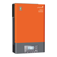
Fig. 9.2: PV connection (all other models)
3. All models except PSW-H-5KW-120/48V, PSW-H-6 .5KW-120/48V and PSW-H-8KW-230/48V:Tighten both PV
terminal screws with a torque of 1. 4 ~ 1 .6 Nm (1.0 ~ 1.2 lbf⋅ft) and make sure the two wires are securely
connected.
CAUTION: Over-tightening the terminal screws can cause damage to the terminal, under-tightening
can cause a loose connection and excessive heat during operation, make sure to use the prescribed
torque. Ensure none of the cable insulation is jammed between the terminal contacts.
4. If using the PSW-H-5KW-120/48V, PSW-H-6.5KW-120/48V or PSW-H-8KW-230/48V, repeatstep 1 and 2 for the
second PV terminal pair and a second PV array, if available.
CAUTION: If using two PV arrays for this model, they must be independent. The positive and negative
terminals of the two PV arrays may not touch each other anywhere in the system.
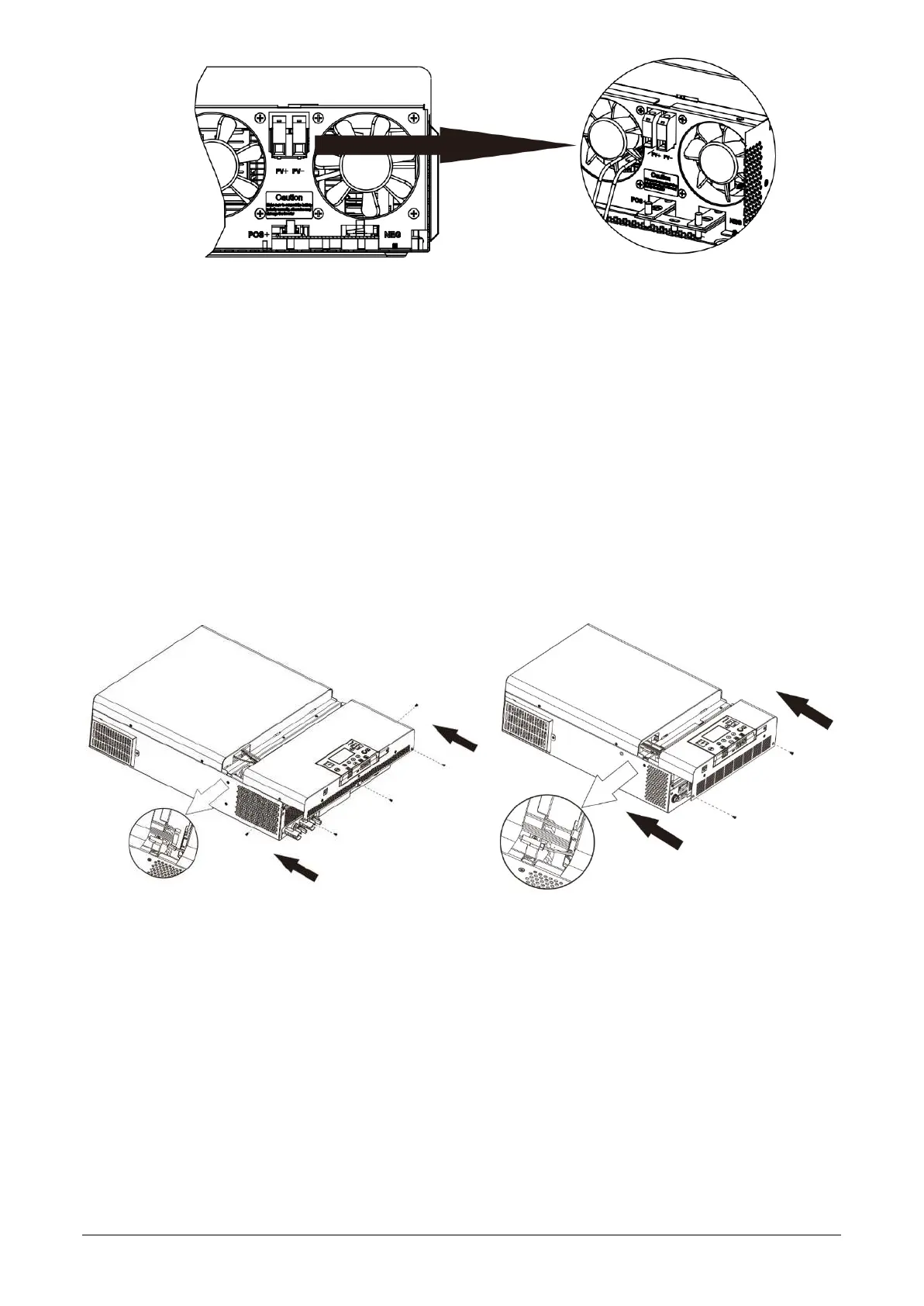
5.7 Final Assembly
After Battery, PV and AC wiring is completed, please slide the b ot tom cover back up on the unit, re-connect the 3
wire harness es removed in Fig. 4, and secure it by fastening the five (PSW-H-5KW-120/48V, PSW-H-6.5KW-120/48V
and PSW-H-8KW-230/48V) or two (all other models) screws as shown below.
PSW-H-5KW-120/48V, PSW-H-6.5KW-120/48V All other models
and PSW-H-8KW-230/48V
Fig. 10: Re-applying bottom cover
5.8 Remote Display Panel Installation
The display module can optionally be removed and installed in a remote locationwith an optional communication
cable. Please take the following steps to implement this remote panel installation. Use a standard straight Ethernet
patch cable (Cat5 or higher) with male RJ45 connectors on both sides(not included). Amaximum cable length of 20
meters or 66 feet is recommended. Follow the steps belowto remove thedisplay moduleand install it away from the
inverter unit.
1. Remove the screw holding the bracket on the bottom of the display module ( Fig. 11 → ①) and push down
the display unit from the case slightly while removing the metal bracket.
2. Keep pushing the display module down,taking care not to damage the connected cable (Fig. 11 → ②).

 Loading...