www.phocos.com 12 | P a g e
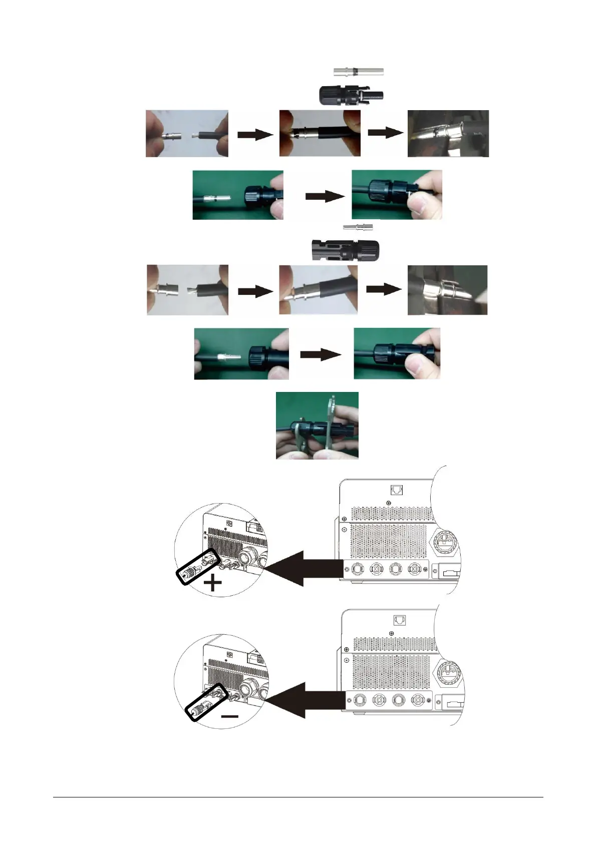
into the “PV-“ terminal (s ee Fig. 9.2).
CAUTION: Ensure correct polarity before connecting. Failure to do so will damage the PSW-H.
Insert stripped PV+ wire into female MC4 p in and crimp:
Insert assembled pin into cor responding connector housing:
Insert stripped PV- wire into male MC4 p in and crimp:
Insert assembled pin into cor responding connector housing:
Tighten both connector domes witha spanner:
Fig. 9.1: PV connection, PV2 input shown as example
(PSW-H-5KW-120/48V, PSW-H-6.5KW-120/48V and PSW-H-8KW-230/48V)

 Loading...