17
4.2.1. Error acknowledgment
Three separate options are available for the error acknowledgment:
Manual (reset button):
• Press the reset button on the front of the device.
If the reset button is still activated after the end of approx. 2 s, the hybrid motor starter will return to the
error state.
If the acknowledgment request (pressed reset button) is pending for more than 6 s, the device switches
to the "Parameterization" state.
Manual (remote acknowledgement point):
• Connect a button (N/O contact) between the MAN and RES terminals.
An acknowledgment is triggered as soon as a positive edge is detected at the MAN input. If a negative
edge is not detected after the end of a period of approx. 2 s, the hybrid motor starter will return to the error
state, since a manipulation or a defect in the acknowledgment circuit cannot be excluded.
Automatic:
• Establish an electrical connection between the RES and AUTO terminals.
After the bimetal monitoring has been triggered and the subsequent cooling, the device performs an au-
tomatic acknowledgement.
The RES terminal block provides voltage for the reset.
For variants with rated control supply voltage of 24 V DC, this is 24 V DC; and for 230 V AC, this is
a special system voltage.
4.2.2. Feedback
As soon as the hybrid motor starter detects an error, the acknowledgment relay is activated, i.e. the N/O
contact will be closed and/or the N/C contact is opened. This response corresponds with that of a motor
protection switch or a motor overload protection relay.
The acknowledgment only serves for signaling and is not a part of the safety chain.
It is therefore not included in the safety observation.
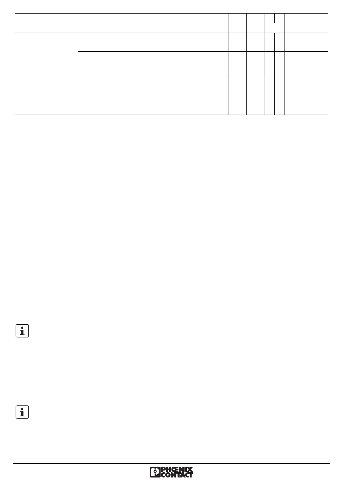
External error
in
the control or
peripherals
(Maintenance
requirement,
NE 44)
Symmetry: The two motor currents deviate by
more than 33
%.
E B A A Manual
Phase failure: One of the two measured motor
currents is zero or the phase shift between the two
motor currents does not equal 120°, but 180°
E B A A Manual
Blockage: The maximum measurable motor
current is exceeded for more than 2 s.
• An error occurred during the reverse running. E B B A Manual
• An error occurred during the forward running. E B A B Manual
Status
Description LED: PWR ERR L R Acknow-
ledgment
 Loading...


