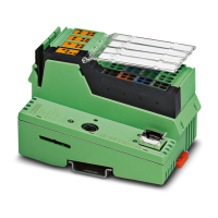
Do you have a question about the Phoenix Contact EV Charge Control Basic and is the answer not in the manual?
Product ordering codes, types, and packaging information.
Detailed technical specifications, supply, interface, and output data.
Details of terminal connections for power, signals, and communication interfaces.
Explanation of LED indicators and their status meanings for device operation.
Settings and functions controlled by DIP switches S1 and S2.
Crucial safety instructions for installation, operation, and handling.
Guidelines for device maintenance, stopping, and proper disposal.
Physical dimensions of the device for mounting and integration.
Instructions for mounting the printed circuit board version of the device.
Instructions for mounting the housing version of the device.
Steps for securely mounting the device onto a standard DIN rail.
Procedures for safely connecting the device to the power supply.
Guidance on connecting the charging contactor for vehicle charging.
Details on controlling the locking mechanism for socket outlets.
Overview of basic device configuration methods.
Explanation of the Proximity Plug signal and its role in charging.
Details on the Control Pilot signal used for charging communication.
Describes connection methods for charging cables according to standards.
Defines vehicle status codes (A-F) and their meanings in charging.
Illustrates the standard step-by-step charging process.
Explains a simplified method for initiating the charging process.
Details the activation mode for the charging controller.
Information on configuring and using the device's digital outputs.
Information on configuring and using the device's digital inputs.
Example setup for charging with local release functionality.
Example for charging with status indication using external LEDs.
Example for charging with current reduction via local release.
Example for charging with local release and locking mechanism.
Example demonstrating charging control using Modbus communication.
Example of controlling charging current using an analog CCR signal.
Example demonstrating charging contactor monitoring.
Example connecting to a residual current monitoring device for safety.
Detailed flowchart of the first charging sequence.
Detailed flowchart of the second charging sequence.
Detailed flowchart of the third charging sequence.
Detailed flowchart of the fourth charging sequence.
Detailed flowchart of the fifth charging sequence.
Detailed flowchart of the sixth charging sequence.
Overview of available Modbus register types (Input, Holding, Coils).
Detailed mapping of device registers to Modbus addresses.
How to assign functions to digital outputs using Modbus registers.
An index of all figures included in the manual.
| Brand | Phoenix Contact |
|---|---|
| Model | EV Charge Control Basic |
| Category | Controller |
| Language | English |


