Connection examples
106377_en_04 PHOENIX CONTACT 35 / 68
7 Connection examples
This section shows some connection examples how the charging controller can be used.
Other options result from the configuration via configuration switches S1 and S2 and the
configuration of the digital inputs and outputs via Modbus/RTU. For the configuration op-
tions, please refer to Table “Configuration switches S1 + S2” on page 13 and “Modbus de-
scription” on page 53.
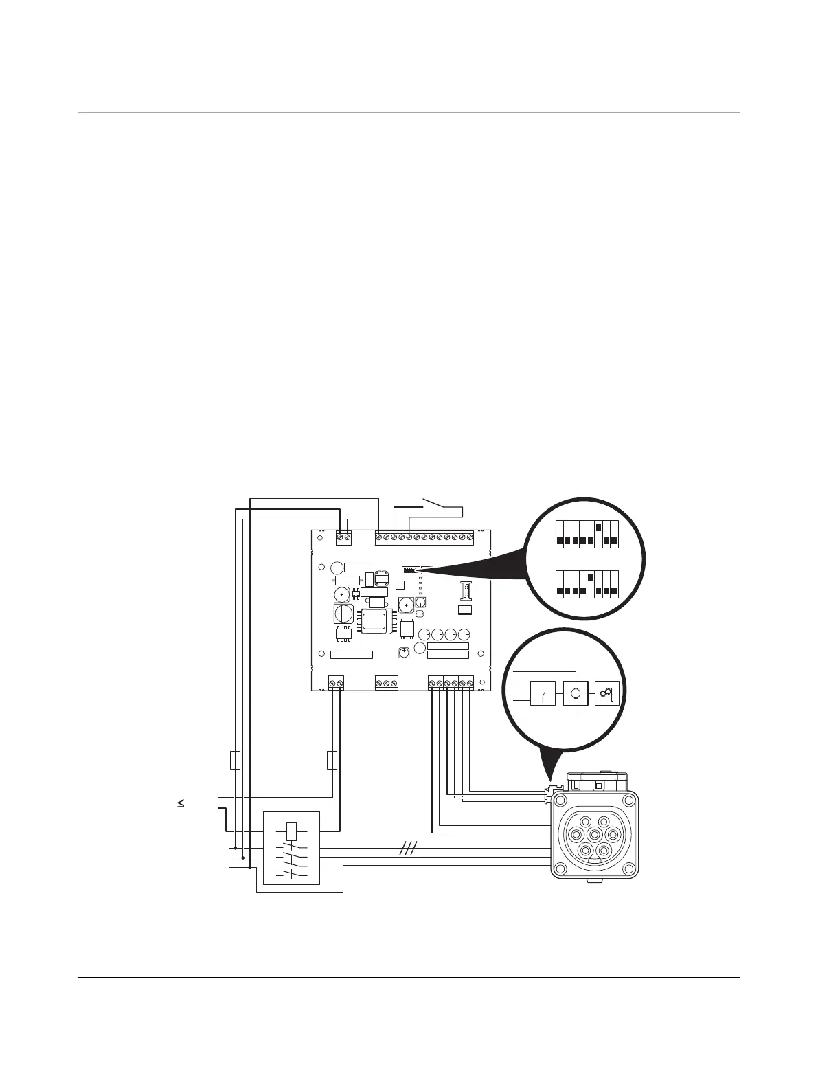
7.1 Charging enabled with local release
Figure 7-1 Connection example 1
S1/DIP 1 = OFF Charging station with Infrastructure Socket Outlet
S1/DIP 6 = ON Charging current preset to 20 A or
S1/DIP 5 = ON Charging current preset to 32 A
Locking is carried out if a vehicle is detected.
The charging process starts if the locking feedback is available, switch k1 is closed, and
status C is present.
L
N
PE
GND
12V
12Va
EN
XR
ML
CCR
IN
OUT
ERR
CHG
CON
C1
C2
A
B
SG
CP
PP
L1D
L2D
L0+
L0-
IO
Relay
R 485S
Outlet
Power
PWR
S1 S2
CON
ERR
CHR
M
RD
GN
YE
BN
N
PE
L, L1-L3
230V
1
3 5
24
6
1A
2A
7
8
k1
1
20 A
S1
0
1
32 A
S1
0
EV-T2M3SE12-3AC...
EV-CC-AC1-M3-CBC-...,
connection of case B