Wiring the outputs and inputs
106377_en_04 PHOENIX CONTACT 31 / 68
6 Wiring the outputs and inputs
The circuits that use lamps and LEDs are only examples. You can also connect other loads,
such as optocouplers, relays or digital inputs of a controller.
6.1 Outputs
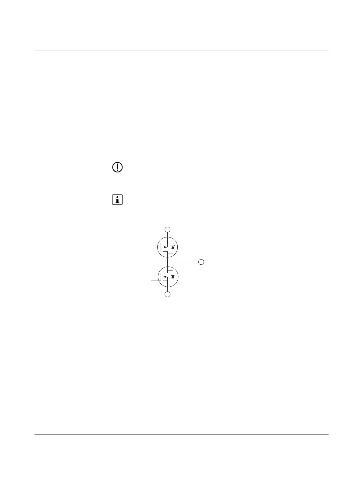
In status 0, the outputs are connected to GND and in status 1 they are connected to voltage
input 12Va. A power supply of 5 V to 30 V DC can be applied at voltage input 12Va.
The maximum current carrying capacity of the switching transistors is 600 mA. If voltage
input 12Va is supplied via the 12 V connection, then a maximum of 500 mA in total are avail-
able at all outputs.
NOTE: Possible damage to the transistors
A supply voltage must never be connected to the outputs, as one of the transistors is
controlled at all times and the transistors would be destroyed as a result.
The outputs are not short circuit proof or protected against overload.
The function of the outputs can be configured. For details, please refer to the Modbus
register description in Section 9.
Figure 6-1 Transistor wiring of the outputs