Flow charts for the charging process
106377_en_04 PHOENIX CONTACT 47 / 68
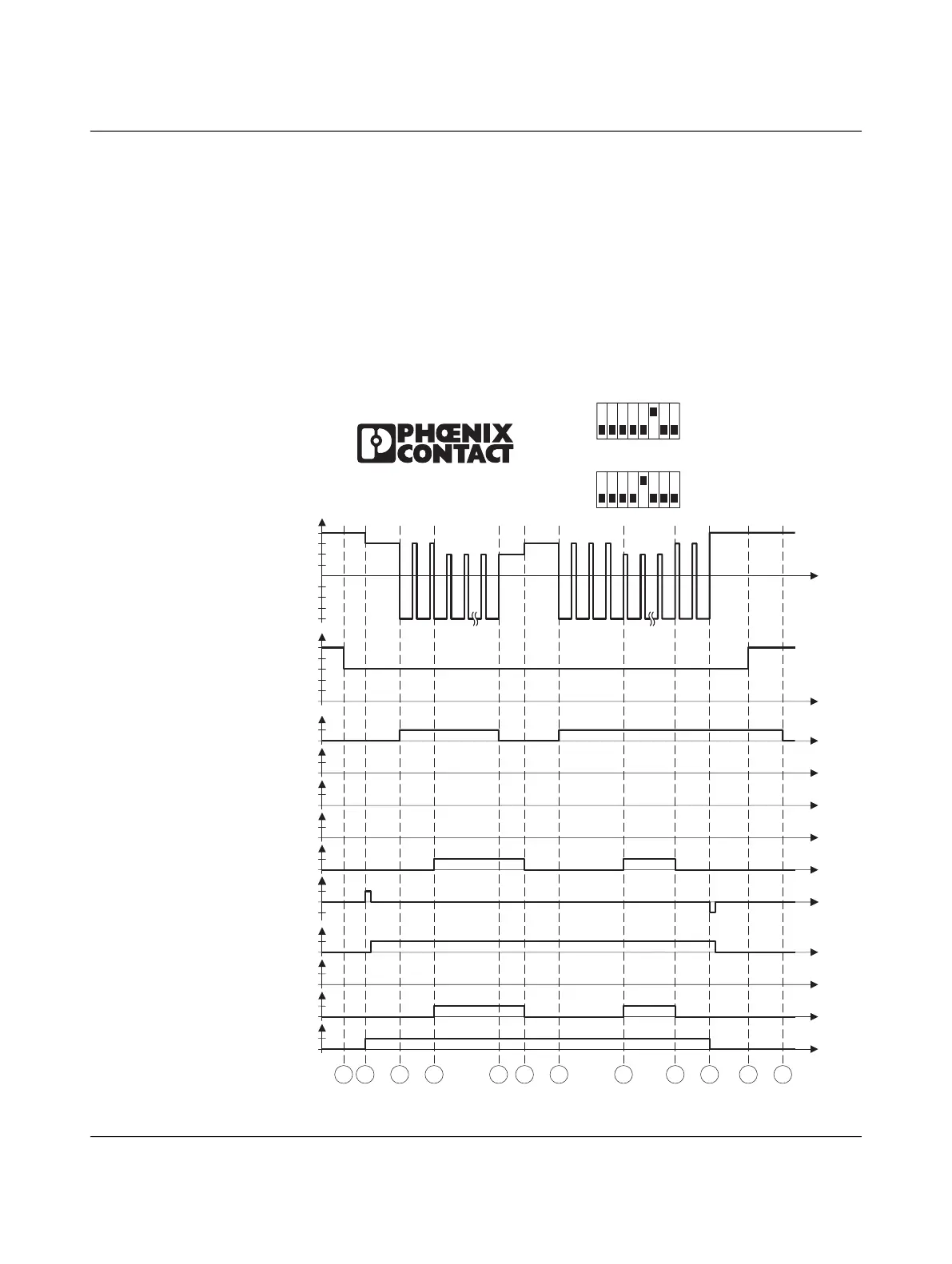
8 Flow charts for the charging process
The examples are based on the default configurations of the digital inputs and outputs.
8.1 Charging sequence 1
Charging sequence according to connection example 7.1, “Charging enabled with
local release”
Figure 8-1 Charging sequence 1
CP
12V
9V
6V
3V
0V
-12V
PP[
Ω
]
1500
680
220
100
0
CCR
1
0
closed
open
1
0
1
0
LD
ERR
EN
1
0
1
0
XR
1
0
ML
CHG
1
0
1
0
CON
+12V
0
-V12
S
1
S
2
S
3
S
4
S
5
S
6
S
7
S
8
∞
EV Charge Control basic
IEC61 1-185
Mode 3
S
9
S
10
S
11
S
12
C1/
C2
LO+/
LO-
1
20 A
S1
0
1
32 A
S1
0
123 45
7
6
8
123 45
7
6
8
S1/DIP 1 = OFF
S1/DIP 5 = OFF
(20 A)
S1/DIP 6 = ON
S1/DIP 5 = ON
(32 A)
S1/DIP 6 = OFF
EV Charge Control Basic