3
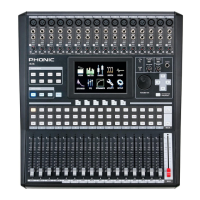
IS16
English
Analog Controls and Settings
Analog Input Section
1. XLR Mic Inputs
TheseXLRmicrophoneinputscanbeusedin
conjunctionwithawiderangeofmicrophones,
such as professional condenser, dynamic
or ribbon microphones, with standard XLR
male connectors. With seriously low-noise
preampliers, these inputs serve for crystal
clear sound replication.
NB.Whenusinganunbalancedmicrophone,
it’s best to ensure that phantom power is
switchedoff.However,whenusingcondenser
microphones the phantom power should be
activated. Check your microphone’s user
manual for information on whether to use
phantom power or not.
2. 1/4” Line Inputs
These 1/4” TRS phone jack inputs accept signals from both
balanced and unbalanced line-level sources. Channels 1 through
16 all feature a single line input jack. It should be noted that
phantom power is not fed to these inputs.
3. Insert Jacks
This1/4”TRSphonejackcanbeusedinconjunctionwithasplit-or
y-cabletoallowanexternaldevice(effectsprocessor,compressor,
etc)tobeusedinconjunctionwiththecorrespondingchannel’s
signal.TheTRS jack’s tip will send the signals to the external
device,while thering will receive the returnsignal backto the
mixer. The sleeve acts as the grounding.
4. PAD Switch
Pushing the PAD switch in will attenuate the signal of the
corresponding channel 20 dB. The PAD button can be found on
channels 1 through 16.
5. Gain Control
TheGaincontrolallowsuserstoadjusttheinputsensitivityofthe
correspondinginput.Linelevelsignalscanbeadjustedbetween
-10and40dB(whenthePADbuttonisengaged),whereasmic
signalscanbeadjustedbetween10and60dB(whenthePAD
buttonisreleased).
6. Peak Indicator
ThisLEDindicatorwilllightupwhenthecorrespondingchannel
reaches 0 dB on the respective channels meter.
Monitoring & Headphones
7. Phones Output
This1/4”TRSphonejackisforsendingstereosignalstoapair
ofheadphones,allowingsignalstobemonitored.
8. Phones Control
ThiscontrolwilladjustthelevelofthePhonesOutput.
9. Control Room Rotary Control
ThiscontrolwilladjustthesignalleveloftheControlRoomoutputs,
found on the rear of the IS16.
2 Track Send and Return
10. Channel 15/16 / 2TR In Button
This button changes the input source of input channels 15 and 16.
Pushing it in will allow channels 15 and 16 to use the signal taken
from the RCA 2TR inputs found on the rear of the IS16. When this
buttonisdisengaged,theXLRor1/4”lineinputjackswillbeused
for these input channels.
11. Control Room / 2TR In Button
Pushing this button in allows users to monitor the RCA 2TR inputs
throughtheControlRoomoutputs.Whenreleased,userswillbe
able to monitor their main stereo signal or Solo signals.
Channel Strips
12. Select Button
This button allows you to select the current channel. The channel
isselected(whetherit’stheinputchannelorthecorresponding
AUX,GrouporMultimix)willdependonyourlayersettings.The
Mainchannelstripalsofeaturesaselectbutton,allowingusersto
adjustthepropertiesoftheMainmix.Theselectbuttonwilllight
up when the corresponding channel is selected.
13. Solo Button
Pushthisbuttonto‘solo’thecorrespondingchannel,sendingitto
the Control Room mix. The solo button will light up when a solo
is activated on a channel.
14. On Button
These buttons will activate the current channel. Activation will be
accompaniedbyanilluminatedLEDwithinthebutton.
15. Faders
These faders will adjust the level of the currently
selected Channel /AUX / Group / Main mix. They
are completely automated, so will revert to their
appropriate positions when layer settings are altered.
Theywillalsoautomaticallyadjusttheirpositionwhen
virtual faders are altered through the GUI.
Mode Buttons
16. AUX (Sends) Fader Mode Buttons
AnyoneoftheseAUXbuttons(from1to 8) willallowusersto
assignAUXsendontochannelfaders.Thiswillallowyoutoadjust
thesignalssentfromeachinputchanneltotheselectedAUXmix.
17. Layer Mode Buttons
These three buttons determine which signals the channel strips
willcontrol.When“CHANNEL”isselected,thechannelstripswill
controlthemaininputsignals(channels1through16),whereas
if“AUX/GP”isselected,thechannelstripswillcontroltheAUX
1to 8 and Group 1to 8 mixes. When “MULTI”is selectedthe
channelsstripswillcontroltheAES/EBUIn,Effect1and2,and
Multi1through8.TheCHANNELandAUX/GPbuttonsbothhave
anLEDthatindicateswhenthelayerisselected(notfeaturedon
theMULTIbutton).
18. Meter Button
TheMeterbuttonallowsuserstojumpimmediatelytothemeter
functioninthetouchscreen’sGUI.
1
2
3
4
5
6
12
13
14
78
10
11
9
15
16
17
18