4
IS16
English
Display
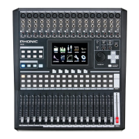
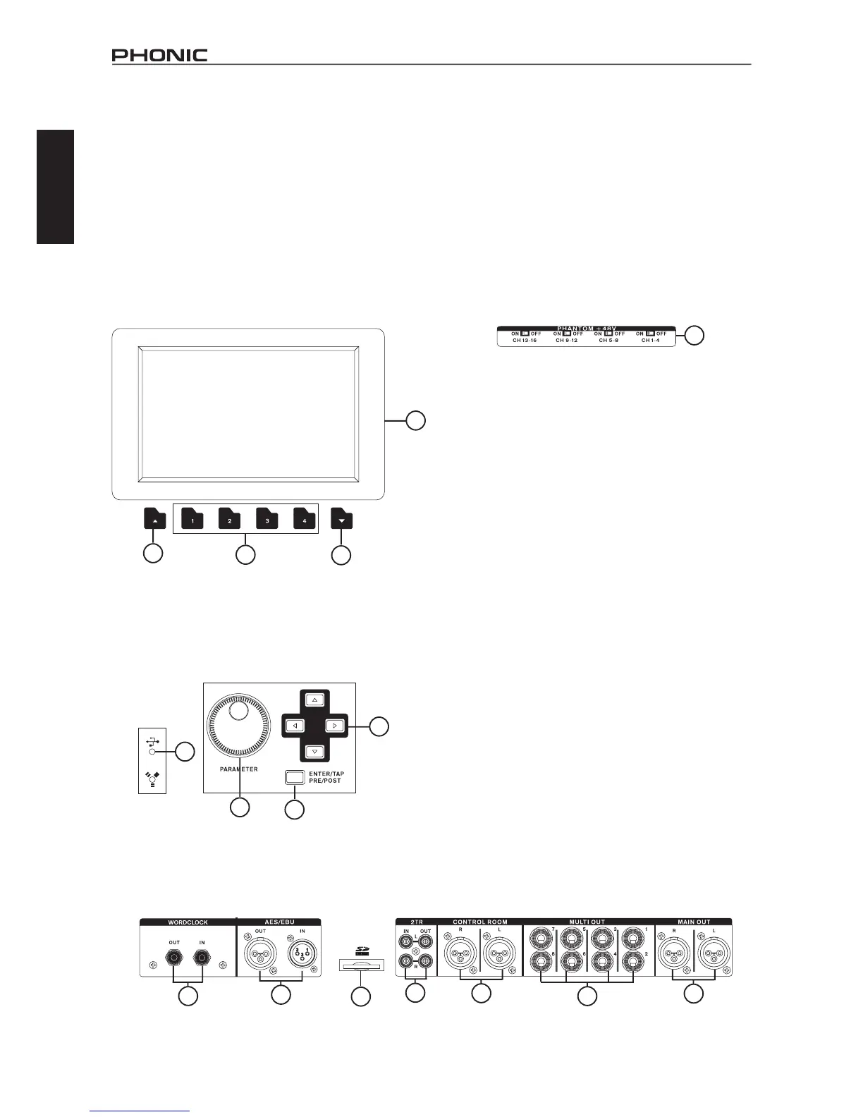
19. LCD Touch Screen
This color LCD touch screen allows users to view and access
various functions on the IS16. The touch screen display has a
power-save feature where it will become dim after 5 minutes of
non-operation.Whenthisoccurs,simplyusethemouseortouch
the screen to reactivate the screen.
20. Function Buttons
These buttons allow users to skip directly to another page/tab of
options on the onscreen display. There may be any number of
pages/tabs available on any given function of the IS16. While the
on-screendisplaycanbeusedtojumpdirectlytothesetabs/pages,
thesebuttonsareavailableforuserswhopreferhardwarebuttons,
orjustwanttousethemforoneoranotherreason.
21. Up and Down Buttons
These buttons will help users scroll or run through all of the
availablefunctionsoftheIS16,theiconsofwhichcanbefound
on the top right-hand site of the GUI.
22. FireWire / USB Indicators
These LED indicators will illuminate when a connection is
established through either the USB 2.0 or FireWire connection.
The mREC FireWire + USB 2.0 Expansion Card will need to be
installedforthistobepossible,however.
Control Section
23. Jog Wheel
Thisjogwheelisusedwhenadjustinganyparameterwithinthe
GUI software. Turning the control clockwise will increase the value
oftheparameter,whileturningitcounter-clockwisewilldecrease
the value.
24. Enter Button
This button is used to select the currently highlighted property
orto conrmedited values within the GUIsoftware.The Enter
buttoncanalsobeusedwhenadjustingtapdelaytimewhenthe
Tap Delay effect is selected.
25. Directional Buttons
These buttons are used to move through the menu on the GUI.
Users can scroll through the various parameter controls and faders
within each individual function menu.
Rear Panel
26. Phantom Power Switches
These grouped phantom power switches allow users to activate
+48V of to feed the Microphone inputs. Phantom Power is grouped
asfollows:channels1through4,5through8,9through12and
13 through 16.
27. Main Outputs
ThesebalancedXLRoutputsareforsendingtheMainLeftand
Right signal of the IS16 out to external devices.
28. Multi Outputs
Thesebalanced1/4”TRSphonejackoutputsareforsendingany
of the input signals or other bus signals out to external devices.
The signal sources of these multi outputs are decided through the
onboard control software.
29. Control Room Outputs
Thesebalanced1/4”TRSphonejacksareforsendingthemonitor
signalstoexternaldevicessuchasactivemonitors.Thesejacks
canalsooutputthe2TRinputsignal,dependingontheselection
of the Control Room / 2TR In button.
30. Stereo 2TR Inputs and Outputs
These stereo RCA inputs and outputs are for sending and receiving
signals to and from consumer-level audio devices such as CD
players,MP3 players andthe like.The 2TInput signal can be
assignedtochannels15and16ortheControlRoomasrequired,
and the Outputs are taken directly from the Main stereo mix.
31. SD Card Slot
TheSDcardslotisusedforsavingandloadingpresets,aswellas
updatingtheIS16’srmware.Firmwareupdatesareaccomplished
by inserting an SD Card and selecting the appropriate Firmware
update option in the Setup menu of the GUI. For the latest
rmware,logontowww.phonic.com.
32. AES/EBU In & Out
These connectors accept and send digital signals from AES/EBU
enabled devices. The AES/EBU input can be assigned to the Main
mixbypushingtheAES/EBUbuttonwithintheGUIsoftware,while
the main signal will be sent to the AES/EBU output.
33. Word Clock In & Out
These BNC connectors send and receive word clock signals to
and from external devices.
19
21
21
20
22
25
23
24
26
27
29
30
28
32
33
31