Installation
Operating Manual PNOZ m B0
1002660-EN-02
16
Information
Please note that at the stated minimum distance, it will be difficult to swap
the chip card from above. If you cannot leave a greater distance, remove
the unit from the mounting rail to swap the chip card.
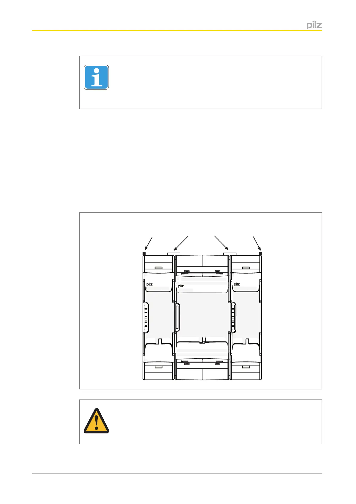
Connecting the base unit and expansion modules
Please refer to the document "System Expansion" for details of the number of modules that
can be connected to the base unit and the module types.
The modules are linked via jumpers.
} Remove the terminator on the side of the base unit and on the expansion module.
} Install the base unit and expansion modules on the mounting rail and connect the units
using the jumper supplied
} Fit the terminator to the unconnected interfaces on the base unit and expansion mod-
ule.
ATTENTION!
Only connect the base unit and expansion modules when the supply voltage
is switched off.
5.3

 Loading...


