Commissioning
Operating Manual PNOZ ms2p HTL
1001401-EN-04
19
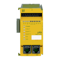
6.2 Pin assignment of RJ45 socket
RJ45 socket
8-pin
PIN Track
1 n.c.
2 0 V
3 n.c.
4 A
5 /A
6 n.c.
7 B
8 /B
6.3 Connection of proximity switches
Proceed as follows when connecting proximity switches:
} Terminals I10 and I11: connect the proximity switch for axis 1
} Terminals I20 and I21: connect the proximity switch for axis 2.
} If only one axis is to be monitored, either terminals I10 and I11 or terminals I20 and I21
will remain free.
} When connecting incremental encoders and proximity switches on one axis:
– Terminals I10: connect proximity switch for axis 1 (I11 is not used)
– Terminals I20: connect proximity switch for axis 2 (I21 is not used)
} The proximity switch must always be connected to a 0 V terminal of the speed monitor.
The 0 V terminals are connected internally.
} Connect proximity switch to 24 VDC of the power supply or the speed monitor (the 24V
terminals of the speed monitor are connected internally)
 Loading...