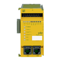
Commissioning
Operating Manual PNOZ ms2p HTL
1001401-EN-04
20
6.4 Connection of the incremental encoder
Proceed as follows when connecting the incremental encoder:
} The incremental encoder may be connected via an adapter or directly to the speed
monitor.
} The incremental encoder on connector X12 monitors axis 1; the incremental encoder
on connector X22 monitors axis 2.
} Use only shielded cables for all connections
} 0 V from the incremental encoder and speed monitor should always be connected.
} Position the terminating resistors of the signal lines as close as possible to the speed
monitor input.
6.4.1 Connect signals of the incremental encoder to the speed monitor
Encoder types: 24 V-HTL
} Apply 24 VDC supply voltage to incremental encoder only
} Do not terminate incremental encoder with Z0=120 Ohm
X12
X22
Speed monitor
24 V DC
0 V
2
4
5
7
8
A
/A
B
/B
24 V
0 V
Incremental
encoder
Fig.: Connection to incremental encoder type 24 V-HTL
6.4.2 Connect incremental encoder to the speed monitor via an adapter
} The adapter is connected between the incremental encoder and the drive. The output
on the adapter is connected to the female RJ45 connector on the speed monitor.
} The adapter can also be used without connecting to a drive.
} The signals relevant for the speed monitor are utilised in parallel by the adapter. The in-
formation stated under "Connect incremental encoder signals to the speed monitor" and
in the adapter operating manual must be observed when connecting the supply voltage.
} Supply voltage (12 V – 30 V) to incremental encoder only.
} HTL signals may not be fitted with a terminating resistor.
 Loading...