EasyManuals Logo

Pilz PNOZmulti User Manual

Pilz PNOZmulti
37 pages
To Next Page IconTo Next Page
To Previous Page IconTo Previous Page
Page #17 background imageLoading...
Page #17 background image
Installation
Installation Manual PNOZmulti Installation Manual
1002265-EN-02
17
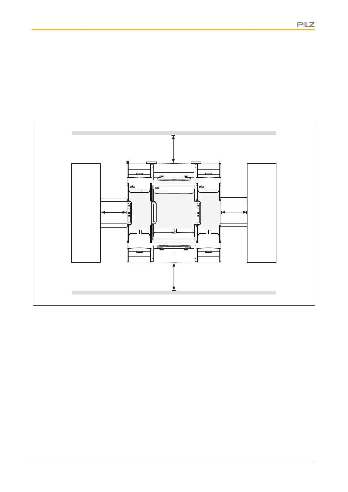
4.1.2 Mounting distances
With control cabinet installation it is essential to maintain a certain distance from the top
and bottom, as well as to other heat-producing devices (see diagram). The values stated
for the mounting distances are minimum specifications.
The ambient temperature in the control cabinet must not exceed the figure stated in the
technical details. Air conditioning may otherwise be required.
Mounting distances:
30 mm
(1.181")
30 mm
(1.181")
20 mm
(0.787")
20 mm
(0.787")
IM0
IM1
IM2 I6
I5
I4IM3 I7
I8
I10 I14
I13
I12I11 I15
X3
X1
X4
X2
PNOZ mm0.1p
T0
T1
T2 O2
O1
O0T3 O3
IM16
IM17
IM18 0 V
A2
A1IM19 24 V
M20
M21
M22 M23
Heat-producing device

Questions and Answers:

Question and Answer IconNeed help?

Do you have a question about the Pilz PNOZmulti and is the answer not in the manual?

Pilz PNOZmulti Specifications

General IconGeneral
PLPL e
Expansion ModulesYes, via base units and extension modules
ProgrammingPNOZmulti Configurator (graphical configuration software)
Safety standardsEN ISO 13849-1, EN 62061, IEC 61508
SILSIL 3
Operating voltage24V DC (typically, but can vary depending on the specific module)
Safety categoryCategory 4

Related product manuals