Installation
Installation Manual PNOZmulti Installation Manual
1002265-EN-02
18
4.2 Install the control system PNOZmulti
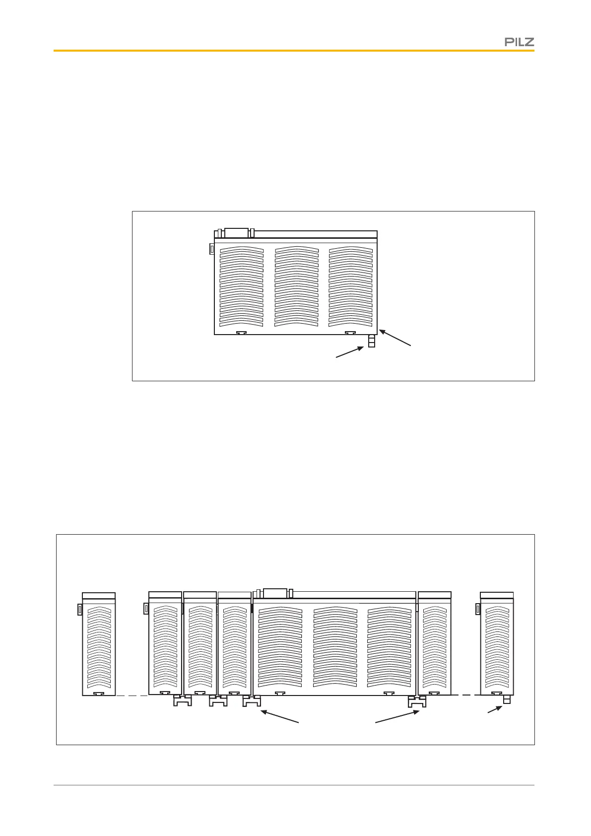
4.2.1 Install base unit without expansion module
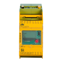
When installed on its own, a base unit from the configurable control system PNOZmulti
must be fitted with a terminator:
} The terminator must be fitted to the side of the base unit marked “Termination/Link”.
} Do not fit a terminator on the left hand side of the base unit.
Terminator
Termination/Link
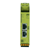
4.2.2 Connect the base unit and expansion modules
The modules are linked via jumpers.
There are 2 pin connectors on the rear of the base unit.
} Make sure that no terminator is fitted.
} Connect the base unit, expansion modules and fieldbus module using the jumpers sup-
plied.
} The terminator must be fitted to the last expansion module to the right of the base unit.
} A terminator must not be fitted to the last expansion module to the left of the base unit.
Expansion module 1 ... 8
Jumpers
Terminator
Fieldbus module
Base unit
Expansion module 1 ... 4
Power supply