Connecting the Control System PNOZmulti
Installation Manual PNOZmulti Installation Manual
1002265-EN-02
35
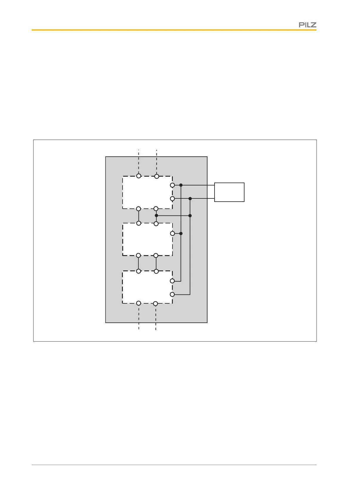
5.13.4 Supply voltage for the cascaded units
} The cascaded PNOZmulti units may be supplied via a power supply. The power con-
sumption of the individual units should be considered when deciding on the size of the
power supply.
} Cascaded PNOZelog units and all PNOZmulti units connected directly to PNOZelog
units must be supplied via a common power supply. The voltage tolerance on the
power supply may be a maximum of +20% or -10%.
S36 (S35)
A2
14 (24) A2
PNOZelog
CI+
CI-
CO+ CO-
PNOZ m1p
CI+
CI-
CO+ CO-
PNOZ m1p
Power
A2
A1
A1
A1
A2
5.13.5 Installing the cascaded units
} If PNOZmulti units alone are being networked, the networked units may be housed in
separate control cabinets.
} If PNOZelog units are integrated into the network, these PNOZelog units and their cas-
cade cables must always be housed in the same control cabinet as the PNOZmulti
units that are connected directly to the PNOZelog units.