Connecting the Control System PNOZmulti
Installation Manual PNOZmulti Installation Manual
1002265-EN-02
31
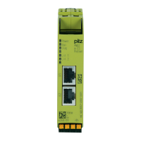
5.11 Fieldbus modules
INFORMATION
When installing the fieldbus modules, please refer to the operating manuals
for the respective unit. You should also refer to the guidelines published by
the user group or fieldbus manufacturer.
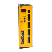
5.12 Link modules
Please note:
} Information given in the "Technical details" of the operating manuals must be followed.
} 2 connection terminals are available for each of the supply connections 24V and 0V.
This means that the supply voltage can be looped through several connections. The
current at each terminal may not exceed 3A.
} The plug-in connection terminals are optionally designed as spring-loaded terminals or
screw terminals (see "Order reference" in the operating manuals).
} You can use ready-made cable from Pilz to connect the devices.
Cable properties
PNOZ ml1p
<-->
PNOZ ml1p
PNOZ ml2p
<-->
Decentralised
modules PDP67
PNOZ mml1p
<-->
PNOZ mml1p
PNOZ mml2p
<-->
Decentralised
modules PDP67
Max. cable length Max. 1000m
Version less than
2.0: Max. 100m
Max. 100m with
shielded cable
Max. 30 m with un-
shielded cable
Max. 1000m Max. 100m with
shielded cable
Max. 30 m with un-
shielded cable
Special require-
ments
4-core shielded,
twisted-pair cable
Connect shield at
both ends, do not
connect to the equi-
potential bonding
bar
Allow for the voltage
drop on the connec-
tion leads (see op-
erating manual)
4-core shielded,
twisted-pair cable
Connect shield at
both ends, do not
connect to the equi-
potential bonding
bar
Allow for the voltage
drop on the connec-
tion leads (see op-
erating manual)
Standards In accordance with
ISO/IEC 11801,
minimum Category
5
In accordance with
ISO/IEC 11801,
minimum Category
5