Connecting the Control System PNOZmulti
Installation Manual PNOZmulti Installation Manual
1002265-EN-02
30
CHIP-Card
1
1
1
1
PE
5
7
1
3
6
7
2
2
9
10
4
4
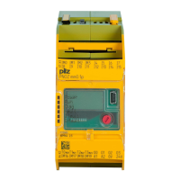
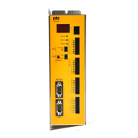
PNOZ ma1p PNOZ m1p
2
8
6
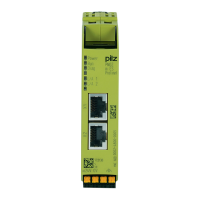
PNOZ ms2p
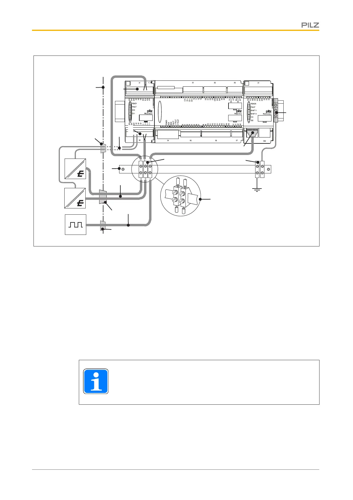
Key:
} 1: Control cabinet wall
} 2: Cable bushing
} 3 Supply voltage for sensors
} 4: Connections for analogue inputs and supply voltage for sensors
} 5: Shield bar
} 6: Sensor signal lines
} 7: Shielded terminal
} 8: Metallised RJ45 connector housing with connected shield
} 9. Terminal for PE
} 10: Earthing terminal
INFORMATION
When installing, always refer to the guidelines of the sensor manufacturer.