Connecting the Control System PNOZmulti
Installation Manual PNOZmulti Installation Manual
1002265-EN-02
28
INFORMATION
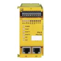
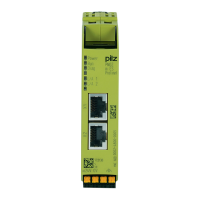
With the RJ45 and Mini-IO plug-in connections, please note that the mech-
anical load capacity of the data cable and connector is limited. Appropriate
design measures should be used to ensure that the plug-in connection is in-
sensitive to increased mechanical stress (e.g. through shock, vibration).
Such measures include fixed routing and strain relief, for example:
– A bending radius of at least 5 x the outer cable diameter should be
maintained on the cable outlet. However, the cables should be kept
as short as possible, taking into account the min. bending radius.
– The cable outlet should be placed face down vertically in order to op-
timise the connector's contact and stability
– The adapter cable/connection cable should be laid flush so as not to
create lateral loads. There should be a lateral offset between the
RJ45 / Mini-IO socket and the cable duct.
– Reduce shock and vibration, for example by:
- separate installation of the control cabinet,
- floating installation of the control cabinet mounting plate,
- mechanical decoupling of: mounting plate, control cabinet feet,
mounting rail, control cabinet attachment to the machine connection
point
- heavy backplate in the control panel
- modifying the position of the motion monitoring module in the con-
trol cabinet
- modifying the speed or ramp gradient
NOTICE
To avoid EMC interference, note the guidelines provided under Electromag-
netic compatibility (EMC) [ 10].