MACHINE PREPARATION
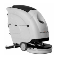
12. INSTRUMENT PANEL COMPONENTS
atic egee command lever (automatic version)
6- Automatic base command lever (automatic version)
7- Battery level / hour-counter display
8- Command button for the monitor of the hour-counter battery level
9- Speed level key
The instrument panel components are identified as follows:
1- Levers to activate brushes/traction (located beneath the grip)
2- Water outlet regulation switch (CDS versions)
3- Detergent outlet regulation switch (CDS versions)
5
8
7
9
5 6
2
3
- Autom sque
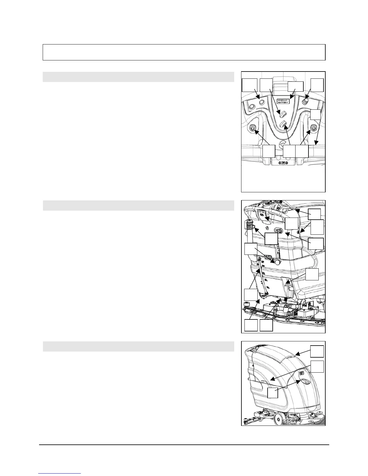
13. REAR
The rear components are identified as follows:
1- Pedal to raise the brushes
ter level tube
ith recovery tank cap
5- Hinges to close
- Screws
7- Lever to raise the squeegee (manual version only)
8- Brake lever
COMPONENTS
2- Wa
3- Solution filter
4- Drainage tube w
the tanks
6 to fix the handlebars
9- Solution tank drainage cap
10- Key and trip unit switch
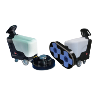
14. SIDE COMPONENTS
T
1
2
8
4
3
6
7
9
10
2
3
5
he side components are identified as follows:
1- Wa
tank
ter solution inlet cap
2- Handle to raise the recovery
3- Handle to raise the suction unit
11