PDP-435PE
27
5678
56
7
8
C
D
F
A
B
E
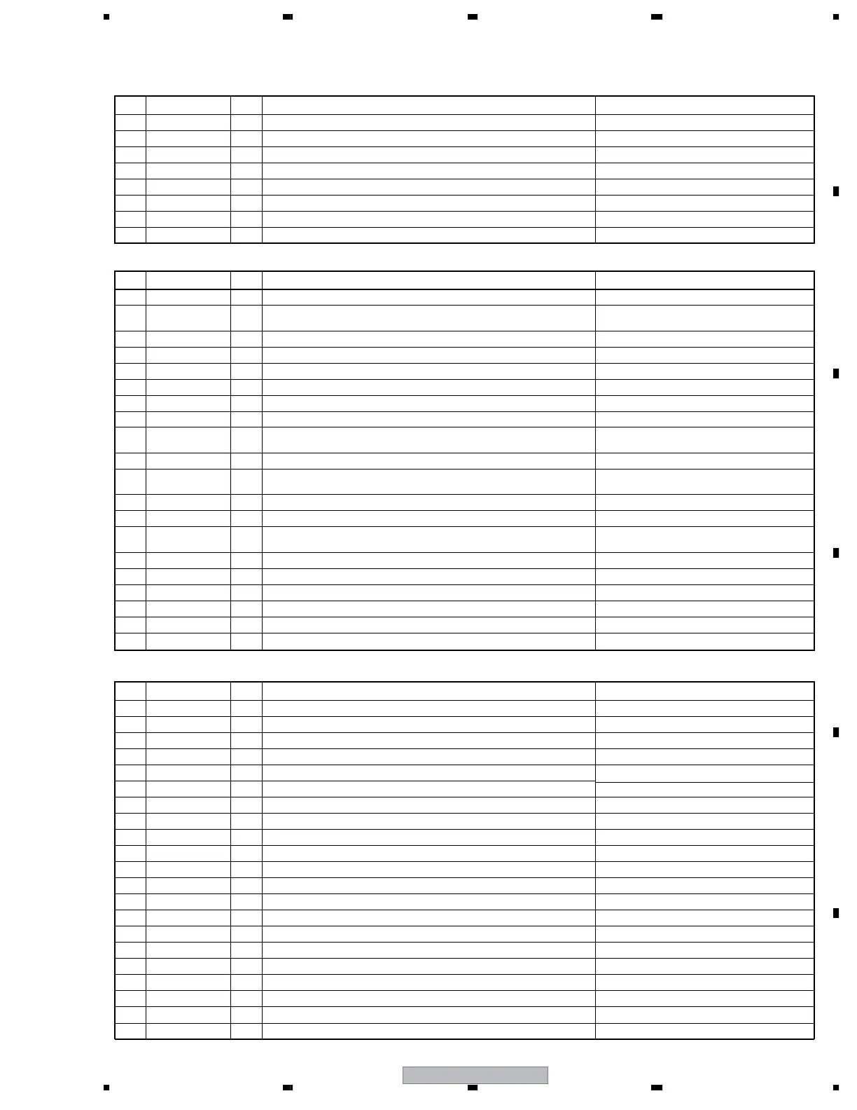
• Voltages
No. Signal Name I/O Signal Description Voltages at NTSC Signal Input
1 6.5V I +6.5V power supply +6.8VDC
2 6.5V I +6.5V power supply +6.8VDC
3 Vcc_GND − GND
4 Vcc_GND − GND
5 STB3.3V I Power supply +3.3V input of module UCOM at panel side +3.3VDC
6 STB_GND − GND
7 STB3.3MUTE O Standby control (+3.3V mute) +3.3 VDC
8 AC_DET I Primary power supply (AC) state input at panel side +3.0VDC
CN4001 (R1) < ⇔ POWER SUPPLY UNIT >
CN4002 (R2) < ⇔ MEDIA RECEIVER >
CN4003 (R3) < ⇔ MEDIA RECEIVER >
No. Signal Name I/O Signal Description Voltages at NTSC Signal Input
1 MR_ST_B I
Connection state detecting signal with MR
0VDC
2 MRXD O
UART communication transmission data with the main UCOM (external PC)
at MR side
0-3.3V amplitude square wave
3 P_ST_B O
Connection state output for the MR
0VDC
4 ACT3V O
Power supply +3.3V output of module UCOM at panel side
+3.3VDC
5 AC_OFF O
Primary power supply (AC) state output at panel side
0VDC
6 GND
−
GND
7 REQ O
Communication request to the main UCOM (external PC) at the MR
0-3.3V amplitude square wave
8 STB3V I
Standby power supply (+3.3V) input from the MR
+3.3VDC
9 KEY_B O
Function key code signal output at panel side
0-3.3V amplitude square wave (at key
operation)
10 MR_ST_B' I
Connection state detecting signal with the MR
0VDC
11 MTXD I
UART communication receive data with the main UCOM (external PC) at
the MR side
0-3.3V amplitude square wave
12 GND
−
GND
13 AUDIO_R I
R ch audio signal input Audio R signal
14 REM_B O
Remote control code signal output
0-3.3V amplitude square wave (at remocon
code transmission)
15 STB_MT I
Standby control input
0VDC
16 GND
−
GND
17 NC
−
Not connected
−
18 FIELD I
FIELD control signal
0VDC
19 GND
−
GND
20 AUDIO_L I
L ch audio signal input Audio L signal
No. Signal Name I/O Signal Description Voltages at NTSC Signal Input
1 RX2- I
DVI signal DVI differential signal (-)
2 RX2+ I
DVI signal DVI differential signal (+)
3 GND
−
GND
4 N.C
−
Not connected
−
5 N.C
−
Not connected
−
6 DDC_SCL I
I2C signal for DDC
0-5V amplitude square wave
7 DDC_SDA I
I2C signal for DDC 0-5V amplitude square wave
8 N.C
−
Not connected
−
9 RX1- I
DVI signal DVI differential signal (-)
10 RX1+ I
DVI signal DVI differential signal (+)
11 GND
−
GND
12 N.C
−
Not connected
−
13 N.C
−
Not connected
−
14 DDC_+5V I
I2C power supply for DDC
+5VDC
15 GND
−
GND
16 HPD O
Hot plug detection
+5VDC
17 RX0- I
DVI signal DVI differential signal (-)
18 RX0+ I
DVI signal DVI differential signal (+)
19 GND
−
GND
20 N.C
−
Not connected
−
21 N.C
−
Not connected
−
 Loading...