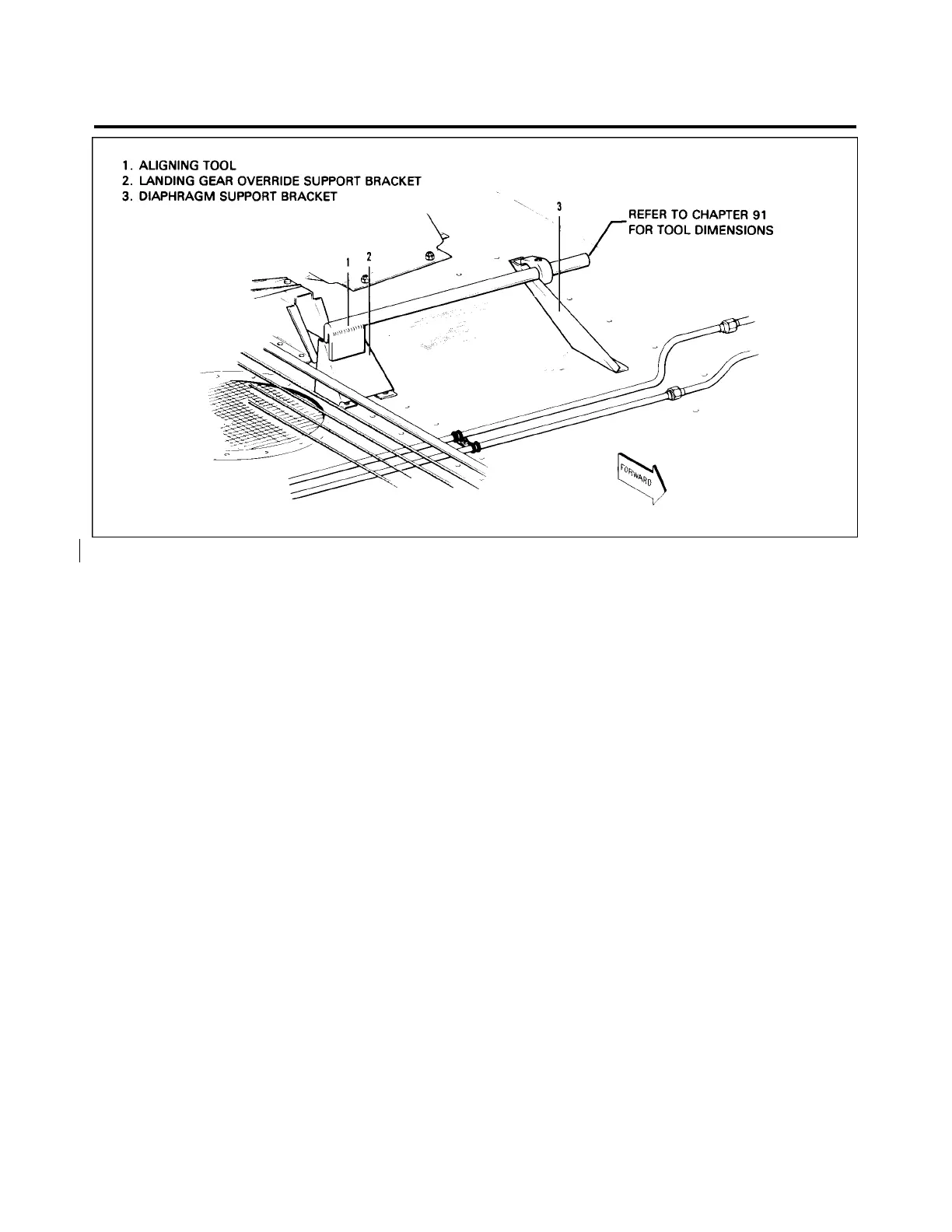
Figure 29-7. Checking Aligning Brackets of Gear Back-Up Extender Actuator
2. Move the actuator on its mounting brackets to allow the manual control push rod to have maximum
clearance from the left stabilator cable and center in the fairlead on the aft face of the main spar box. Check
system for sufficient travel and freedom of movement of controls. Tighten actuator attaching screws.
—NOTE—
Care should be used when attaching the forward hose to the
diaphragm assembly so that no strain is placed on the teflon
bushing and diaphragm shaft, thus causing friction in movement.
3. Connect the hydraulic lines to the elbows of the actuator hydraulic valve.
—NOTE—
A special fitting with a restriction orifice of .063 of an inch is
installed in the side of the hydraulic valve. Do not mistake this for
a standard AN fitting.
4. Connect the pressure and static hoses to the elbows of the diaphragm housing. Secure hoses with
clamps.
5. Connect the actuator electrical leads terminal to their mating terminals and insulate. Refer to the
electrical schematic for hookup.
6. Check the actuator adjustments as given in Check and Adjustment of Gear Back-Up Extender
Actuator.
7. Install the rear seat.
29-10-10
Page 29-23
Revised November 6, 1979
2C17
PIPER AIRCRAFT
PA-28RT-201 / 201T
MAINTENANCE MANUAL
 Loading...


