Electronics Overview and Specifications
This kit provides sensors, motors, and a motor controller board for interfacing with myRIO and creating mechatronic
systems. This section provides overview and specification information for each electronic component. For the motor
controller board, it provides an overview and diagram all the ports contained on the board. For each sensor and motor, it
provides a brief overview, links to specifications and resources, and specifications of the particular motor controller port.
To set up and test each sensor and motor, see the following section. To learn more about the provided sensor and motors,
as well as other sensors, actuators, and interfaces you can use with myRIO, check out the myRIO Project Essentials Guide:
http://www.ni.com/tutorial/14621/en/ .
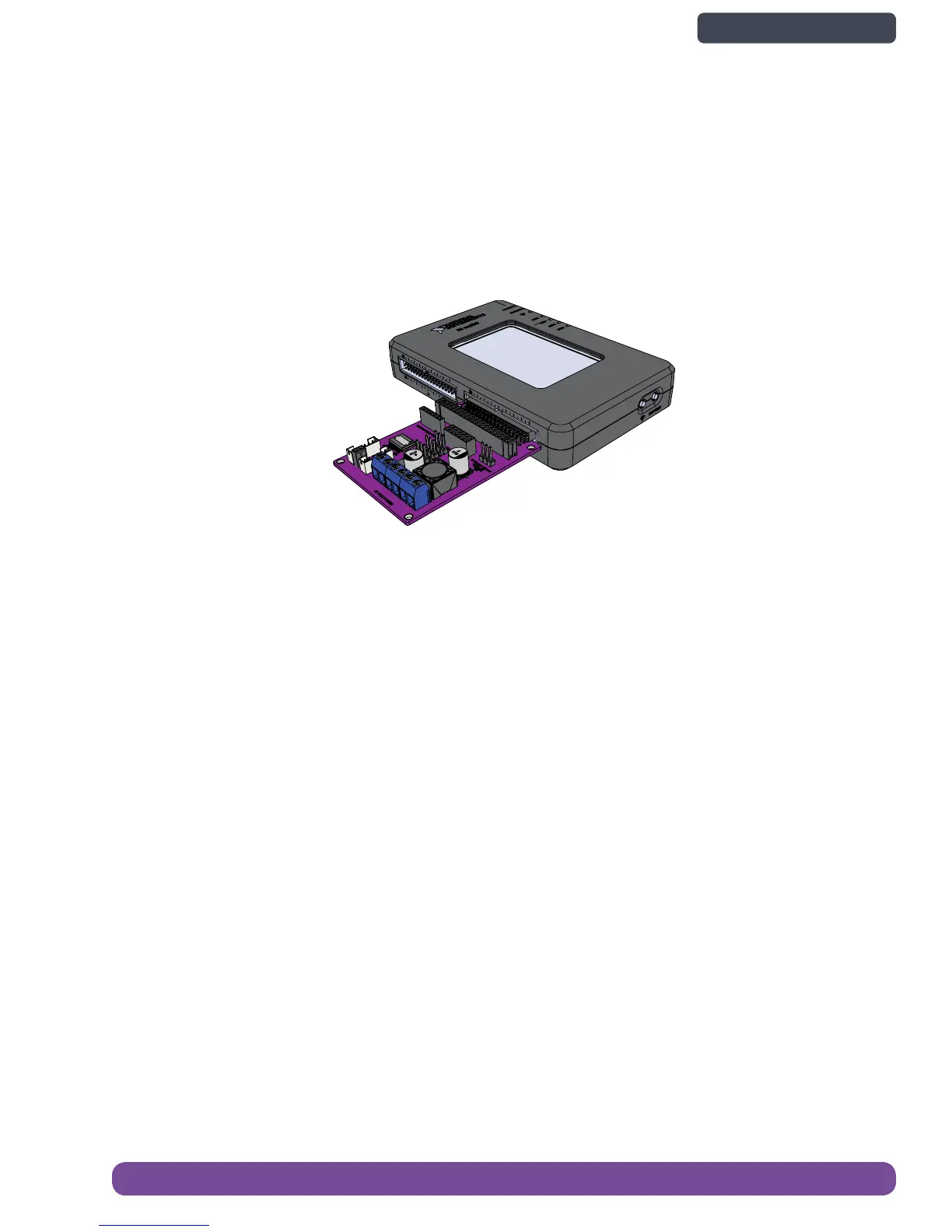
myRIO Motor Controller Board
The purpose of the motor controller board is to provide extra power and signal conditioning to motor output signals, while
also providing protection to myRIO. It also breaks out all the pins needed for the sensors in the kit so that they are easier
to connect to. It connects directly to the 34 pin myRIO Extension Port (MXP). myRIO has two identical MXP ports, A and B.
The motor controller board can be connected into either port. The signals are distinguished in software by the connecto r
name, as in ConnectorA/DIO1 or ConnectorB/DIO1. Refer to the software documentation for information about configuring
and using signals
The pin outs on the myRIO motor controller board are designed to be used with the sensors and actuators used in the kit,
but can also be repurposed for other sensors and actuators depending on their specifications and connectors. See the
figure below for port locations, and the next few pages for detailed port descriptions.
Electronics Overview and Specications 35
Back to Contents page