Servo Motor
2x
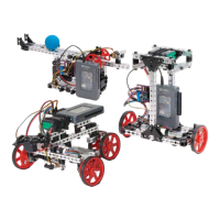
Standard Servo 40538
Servo Number
(noted on motor
board)
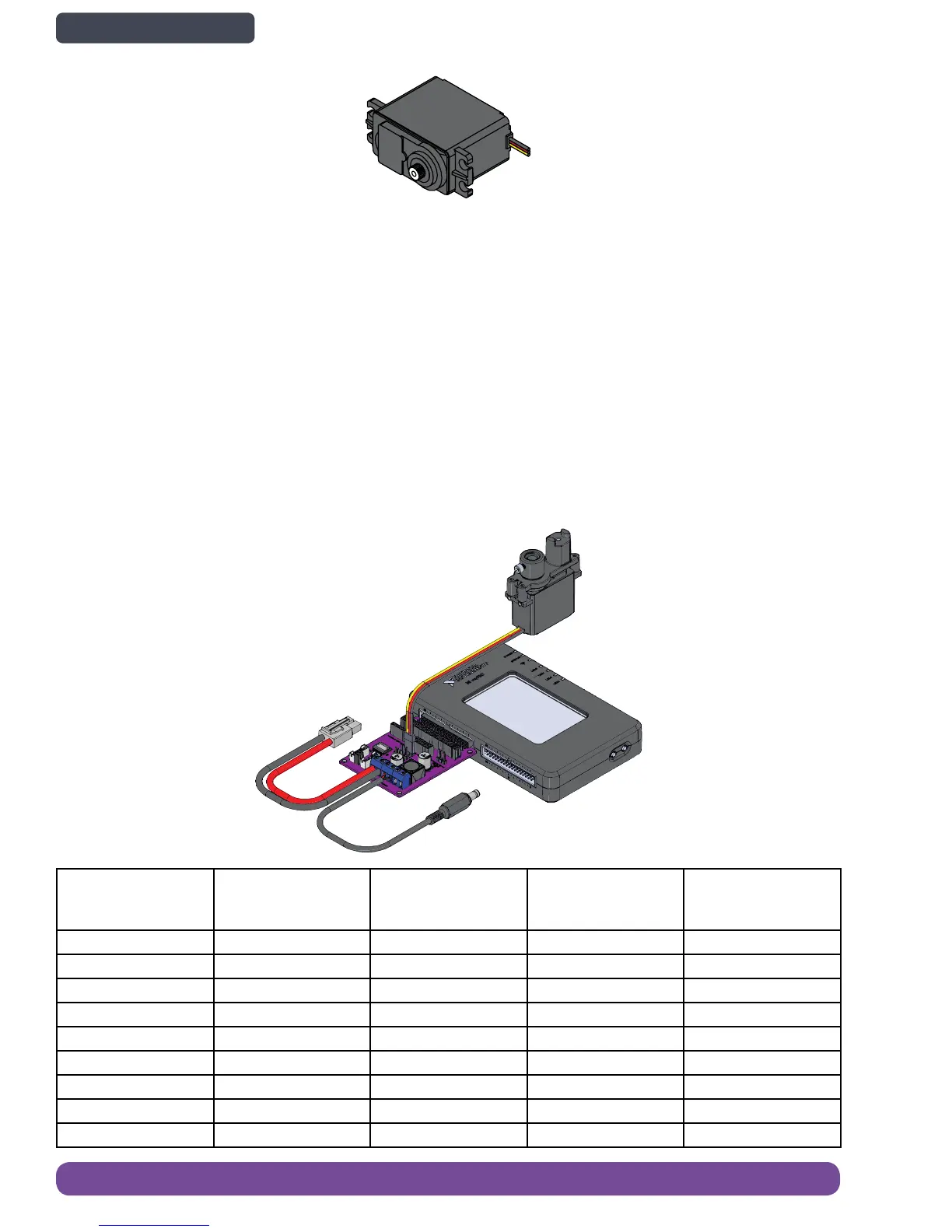
Pin Name (from left
to right based on the
image above)
Wire color (if using
provided servo
motor)
MXP Pin number
Name in software
(based on MXP A)
0 Signal Yellow 27 A/PWM0
0 VCC Red n/a n/a
0 Ground Black 6 n/a
1 Signal Yellow 29 A/PWM1
1 VCC Red n/a n/a
1 Ground Black 6 n/a
2 Signal Yellow 31 A/PWM2
2 VCC Red n/a n/a
2 Ground Black 6 n/a
The servo motor provides motion control. Pulse-width modulation (PWM) is used to control the position of the motor shaft.
Internally, the servo combines a DC motor, gearbox, potentiometer and controller electronics to provide relatively precise
angular position. The servo included in the kit is a standard servo, which means it can rotate about 180 degrees. The
pinout of the servo motor includes power, ground, and the PWM signal line.
Learn More
• Specifications: https://www.pitsco.com/HS-322HD_Standard_Servo?ap=10118-8049
• Project Essentials Guide, chapter 17: http://www.ni.com/tutorial/14621/en/
Servo Motor Output Port
The motor controller board contains circuitry to provide more power and extra protection for the connected servos.
• Servo Channels: 3
• Servo Power Voltage: 6 volts DC
• Continuous Output Current: 1 amp per channel, 3
amps total servo channels combined
• Peak Output Current: 6 amps (total for all 3 servo
channels combined)
40 Electronics Overview and Specications
Back to Contents page