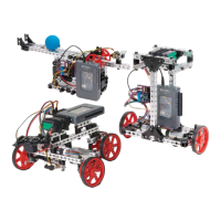
DC Motor and Encoder
The geared DC motor provides speed control. It receives a differential analog voltage signal, which proportionally controls
the angular velocity of the motor shaft. To maximize power efficiency and motor torque, we use PWM signals to control the
speed of the DC motor, and a digital line to control the direction. The signals are converted to differential analog voltage by
the motor controller board, which is described in more detail below.
The DC motor also includes a built-in quadrature encoder. The encoder provides feedback for the motor shaft’s speed and
position. The encoder pinout includes power, ground, and two digital signal lines.
Learn More
• Specifications: http://store.digilentinc.com/dc-motor-gearbox-1-53-gear-ratio-custom-6v-motor-designed-for-
digilent-robot-kits/
• Project Essentials Guide, chapter 18: http://www.ni.com/tutorial/14621/en/
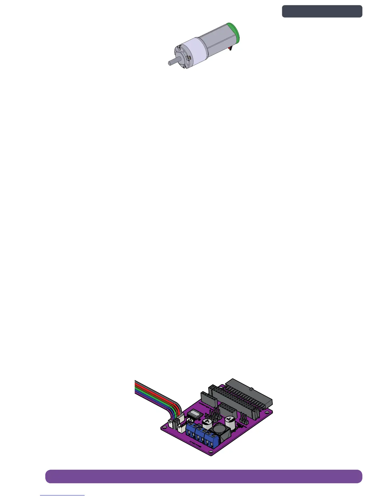
DC Motor and Encoder Output Port
For each DC motor, the motor controller board receives a PWM signal for speed control and a digital signal for direction
control. It contains a full bridge motor driver (with protection circuitry) to convert the PWM and digital signals to a
differential analog voltage signal, which is passed to the DC motor. Though it can be repurposed for other motors, the port
is designed for the DC motor in the kit, which includes a built in encoder.
The myRIO MXP port only contains one set of quadrature encoder input pins. On the motor controller board, these pins are
wired to the Motor 1 encoder port. For the Motor2 port, the encoder pins are instead connected to a header port. Jumper
wires can be used to connect the pins of the header port to the set of quadrature encoder pins on the opposite MXP port
(MXP B if the motor board is connected to MXP A and vice versa).
• Motor Channels: 2
• H-Bridge Chip: TI DRV8432 Dual Channel Full-Bridge PWM Motor Driver
• Motor Voltage Output: 6 volts DC
• Continuous Output Current: 6 amps (total for both motor channels combined)
• Peak Output Current: 9 amps (total for both motor channels combined)
• PWM Operating Frequency: Up to 500 kHz
• Duty Cycle: 0 – 99%
• Integrated Self-Protection Circuits: Under Voltage, Over Temperature, Overload and Short Circuit
• On-board Over Temperature LED Indicator (OT) – also pinned to myRIO DIO13
2x
Digilent DC Gear Motor 41143
Electronics Overview and Specications 41
Back to Contents page
 Loading...