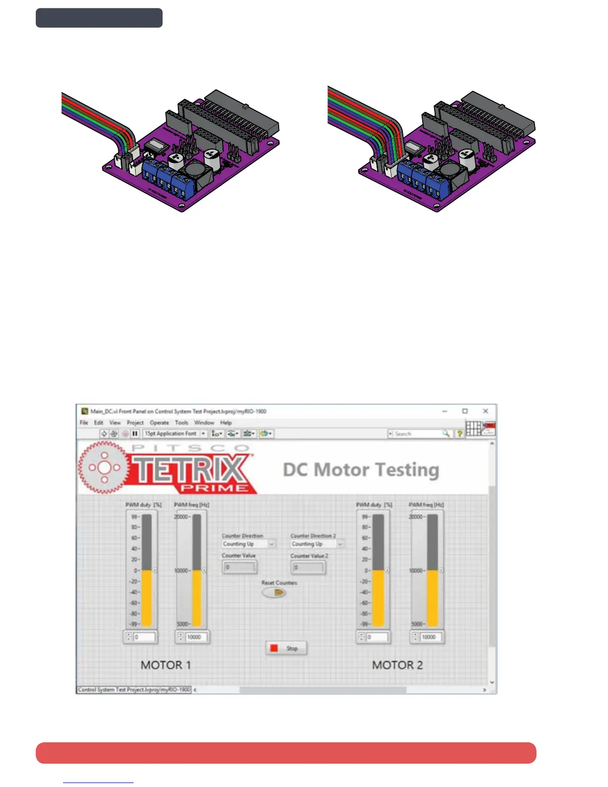
Step 2: For the Motor2 port, the encoder pins are instead connected to a header port. To connect the Motor2 encoder,
use jumper wires to connect pins of the header port to the set of quadrature encoder pins on the MXP port B. Pin A of the
header port should connect to MXP B pin 18. Port B of the header port should connect to MXP B pin 22.
Step 3: Insert the motor board into myRIO MXP A, plug the battery cable into the battery, and plug the DC connector into
the myRIO power port to power it on. Allow myRIO about 30 seconds to boot.
Step 4: After completing the LabVIEW and myRIO Setup instructions, navigate to “…\Desktop\National Instruments\Pitsco
Tetrix Prime for NI myRIO\Test Code” and open “Control System Test Project.” Connect to myRIO by right clicking myRIO-
1900 and clicking connect. Allow a few moments to connect. Expand the myRIO dropdown, and navigate to “Testing Your
System > Main_DC.vi.” Feel free to explore the code on the block diagram by pressing Ctrl + E, and then press Ctrl + E again
to return to the front panel.
Set Up and Test the DC Motor and Encoder
Step 1: Connect both DC Motors to the motor controller board using DC Motor ports 1 and 2.
50 Control System Set Up and Testing
Back to Contents page