Installation, use and maintenance
M0546
24 /6 0
14.4 ELECTRICAL CONNECTIONS
ELECTRICAL
CONNECTIONS
The electrical connections must be carried out in a workmanlike manner by
specialised personnel, in full compliance with the regulations in force in the
country of installation and with the instructions in the electrical diagrams in
this manual.
IMPORTANT
The CUBE B.SMART Electronic Panel is NOT equipped with circuit
breakers; it is therefore essential to install upstream CUBE B.SMART
an electrical power supply panel equipped with a circuit breaker /
disconnector with a current rating suitable for the electrical line and a
differential switch suitable for the type of electrical load.
Otherwise, provide for a quick disconnection system such as a socket/plug
connection to be used in the event of faults.
IMPORTANT
Before accessing the electrical parts, make sure that you have
disconnected all the main switches that energize the unit.
The operations required for a correct wiring are described below:
• Opening CUBE
• Opening the rear cover of the controller
• Closing the rear cover of the controller
• Closing CUBE
OPENING
CUBE
OPENING THE
REAR COVER
OF THE
CONTROLLER
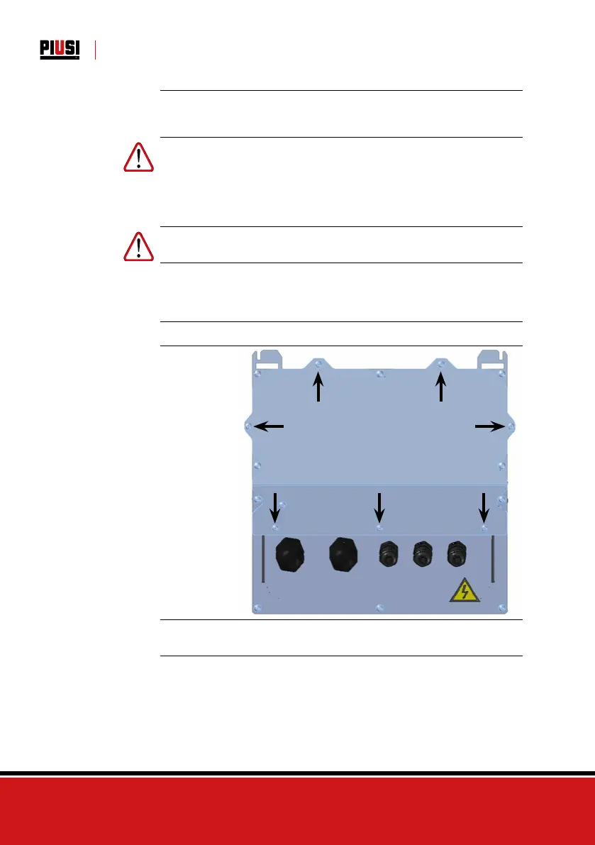
Loosen all 7 screws of the rear cover of the controller to access the
compartment of the electronic boards
CABLE GLAND
CONNECTION
Cable gland connection: the cable glands to be used for the various
signals are indicated in order to obtain an optimised cable route inside the
controller Pulser input and motor output are already wired.