17/124
EN
17 /6 0
This manual belongs to PIUSI S.p.A. The reproduction of all or parts is prohibited.
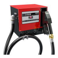
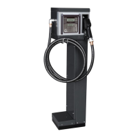
CUBE
EN (translated from Italian)
12 TECHNICAL SPECIFICATIONS
INTENDED USE Implementation of a system for the dispensing and control of fluids for
private use not subject to special regulations such as ATEX for potentially
explosive environments.
IMPORTANT
DO NOT INSTALL CUBE B.SMART IN ENVIRONMENTS CLASSIFIED
AS POTENTIALLY EXPLOSIVE IN ACCORDANCE WITH ATEX
REGULATIONS.
MAXIMUM
VARIATIONS IN
ELECTRICAL
PARAMETERS
The Motors in the fuel dispensers accept maximum variations:
of supply voltage of +/- 5% and maximum variations of frequency of +/- 2%
SEE TECHNICAL SPECIFICATIONS TABLE BELOW
IMPORTANT
BEFORE INSTALLATION, ALWAYS CHECK THAT YOUR MODEL IS
CORRECT AND SUITABLE FOR THE SUPPLY EFFECTIVELY AVAILABLE
(VOLTAGE / FREQUENCY).
Signal Standard
conditions
Limits Notes
Power supply
input
220 V ac – 240 V
ac for 230 V ac and
50 Hz
900 W - 4.2 A
The electronic board is equipped with
a switching technology power supply
that allows a wide range of voltages
and frequencies and therefore makes
the equipment robust for the high
fluctuations of voltage or frequency
present on the power distribution mains
in many areas of the world
Electronic Key
Interface
YELLOW key
(iButton): Enabling
input by PIUSI
electronic key
Through a software pro-
cedure, the yellow keys
of the drivers are reg-
istered on the PC and
then these drivers are
enabled on one or more
dispensing stations
You can configure whether or not
such a key is present
Level 1 contact
input
(only for
versions where
available)
Clean contact or
Open Collector
(NPN) electronic sig-
nal If it is necessary
to supply a level sen-
sor, 24 V dc are also
available on the ter-
minal. The maximum
current available to
the sensor for its pow-
er supply is 25 mA
About 1 mA at 5 V dc
will be supplied on the
clean contact (or on
the open collector)
It is possible to configure whether or
not this signal is present, and it is also
possible to configure the type of signal
(normally open or normally closed
for versions where provided) Finally,
it is possible to choose the action to
be taken by the controller when it
receives this signal: it can only give an
alarm on the display or it can totally
inhibit other dispensings if the Pump
Block is set
Level 2 contact
input
(only for
versions where
available)
Clean contact or
Open Collector
(NPN) electronic sig-
nal If it is necessary
to supply a level sen-
sor, 24 V dc are also
available on the ter-
minal. The maximum
current available to
the sensor for its pow-
er supply is 25 mA
About 1 mA at 5 V dc
will be supplied on the
clean contact (or on
the open collector)
It is possible to configure whether or
not this signal is present, and it is also
possible to configure the type of signal
(normally open or normally closed
for versions where provided) Finally,
it is possible to choose the action to
be taken by the controller when it
receives this signal: it can only give an
alarm on the display or it can totally
inhibit other dispensings if the Pump
Block is set