10 ATR171 - User manual
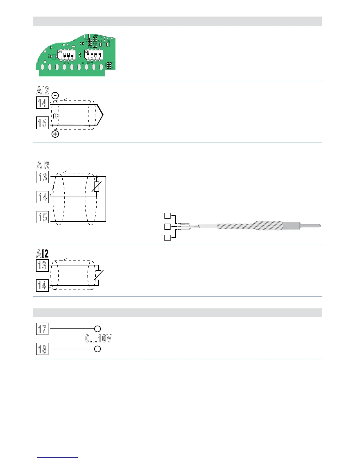
5.1.c Analogue input AI2 (only for ATR171-23ABC-T)
To enable the second analogue input, set the dip
switches as indicated in the figure.
In this configuration the serial RS485 is not available.
14
15
TC
Shield/Schermo
For thermocouples K, S, R, J.
• Comply with polarity.
• When extending thermocouples be sure to use the
correct extension/compensating cable.
• When shielded cable is used, it should be grounded at
one side only.
13
14
15
Shield/Schermo
PT/NI100
For thermoresistances PT100, NI100.
• For a three-wires connection use cables with the same
diameter.
• For a two-wires connection short-circuit terminals 13
and 15.
• When shielded cable is used, it should be grounded at
one side only.
WHITE / BIANCO
RED / ROSSO
13
14
Shield/Schermo
PTC/NTC
For thermoresistances NTC, PTC, PT500, PT1000 and
linear potentiometers.
When shielded cable is used, it should be grounded at
one side only.
Examples of connection for linear input
17
0...10V
+
-
For linear signals 0..10 V.
Comply with polarity.

 Loading...


