User manual - ATR171 9
5.1.a Power supply
2
SUPPLY
24...230V
AC/DC
Switching supply with exstended range 24..230 Vac/dc
±15% 50/60 Hz – 5,5 VA.
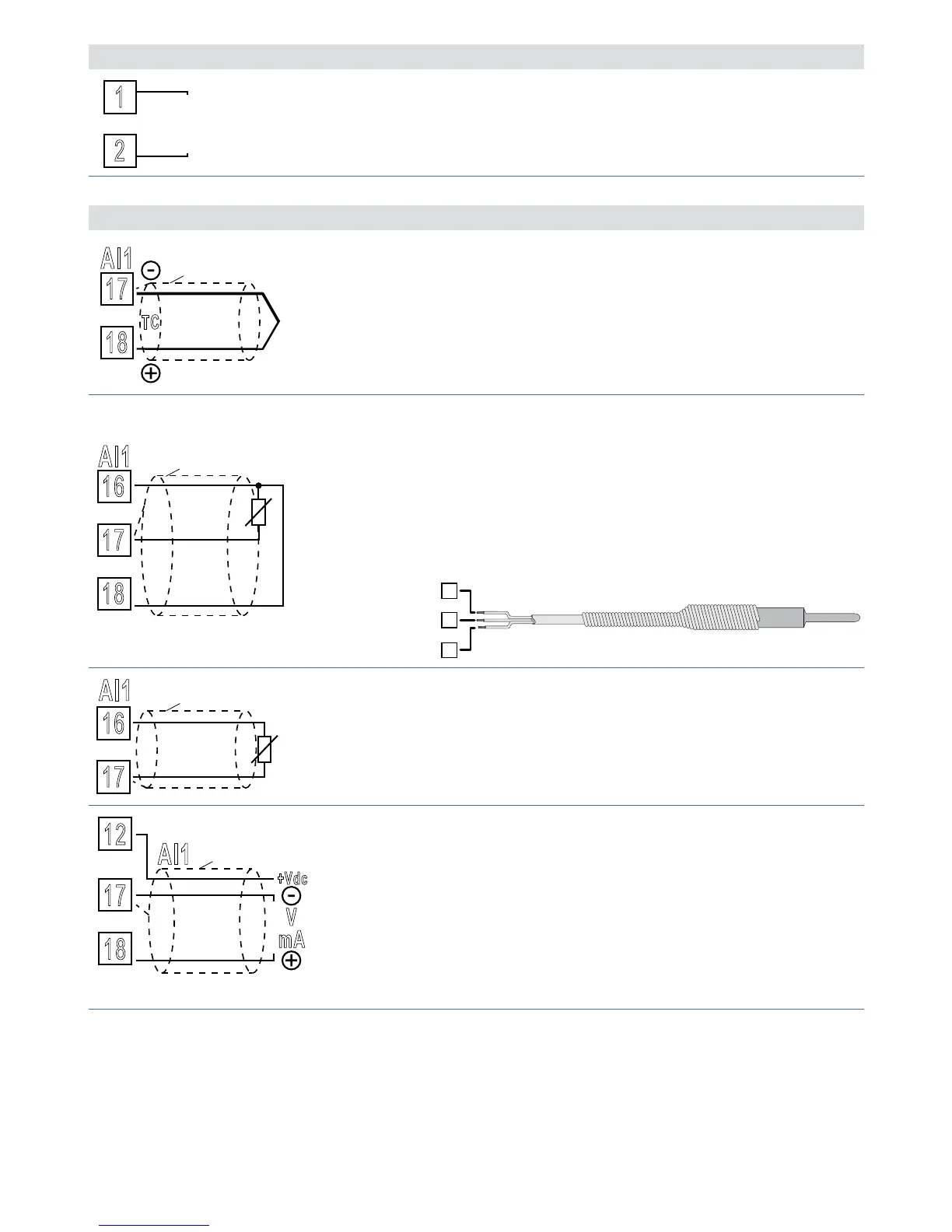
5.1.b Analogue input AI1
17
18
TC
Shield/Schermo
For thermocouples K, S, R, J.
• Comply with polarity.
• For extensions make sure to use the correct extension/
compensating cable.
• When shielded cable is used, it should be grounded at
one side only.
16
17
18
Shield/Schermo
PT/NI100
For thermoresistances PT100, NI100.
• For a three-wires connection use cables with the same
diameter.
• For a two-wires connection short-circuit terminals 16
and 18.
• When shielded cable is used, it should be grounded at
one side only.
18
17
16
WHITE / BIANCO
RED / ROSSO
16
Shield/Schermo
PTC/NTC
For thermoresistances NTC, PTC, PT500, PT1000 and
linear potentiometers.
When shielded cable is used, it should be grounded at
one side only.
12
17
18
AI1
V
mA
+Vdc
Shield/Schermo
For linear signals Volt / mA.
• Comply with polarity.
• When shielded cable is used, it should be grounded at
one side only.