54 ATR171 - Manuale d’uso
P :0...100mbar
Pmax :3bar
T :0..70°C
OUT : 4...20mA
IN :9...33V DC
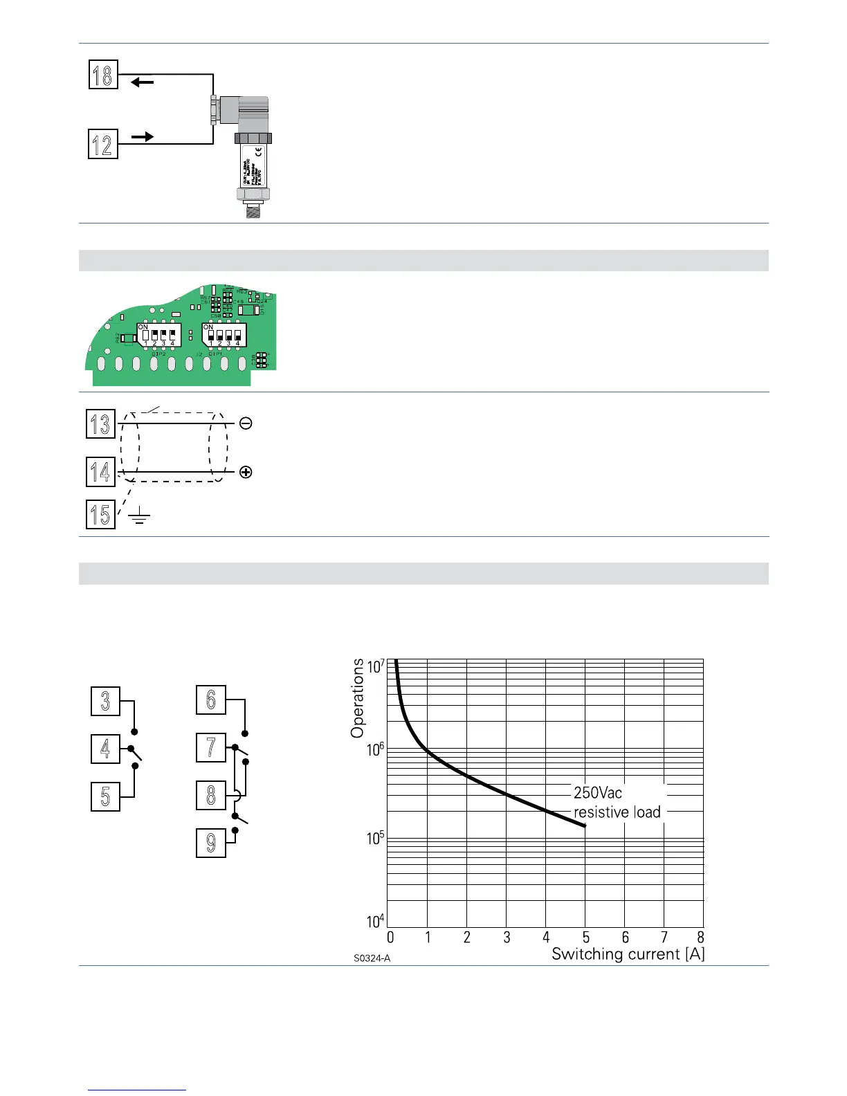
18
12
4...20mA
Per segnali normalizzati in corrente 0/4..20 mA con
sensore a due fili.
Rispettare le polarità:
C= Uscita sensore
A= Alimentazione sensore
5.1.e Ingresso Seriale (solo per ATR171-23ABC-T)
Per abilitare la seriale RS485 impostare i dip switch
come in figura.
In questa configurazione il secondo ingresso analogico
NON è disponibile.
13
Comunicazione RS485 Modbus RTU.
Per reti con più di cinque strumenti alimentare in bassa
tensione.
5.1.f Uscita Relè Q1, Q2, Q3
3
4
5
Q1
8A
230V
1/2HP
Portata contatti:
8 A, 250 Vac, carico resistivo 10
5
operazioni;
30/3 A, 250 Vac, cosφ= 0.3, 10
5
operazioni.
 Loading...


