10 - ATR144 - User manual
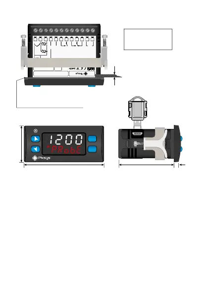
5 Dimensions and installation
+V
8 9
10 11 12
1 2 3 4
5
6 7
5A 23 0V
Res istiv e
1/8 HP
Q2
Cla ss 2
sou rce
24. ..230 V
AC/ DC
5A 23 0V
Res istiv e
1/8 HP
Q1
DI/ O1
(NP N)
PTC
NTC
-
+
Tc
I
V/I
+
-
PT/ NI100 /1K
2 wir e 4/20m A
Pow er
ATR144-ABC
MADE IN
EU
ATR144
FNC
SET
77 mm 953 mm
35 mm
Gasket for 32x74
Guarnizione per 32x74
Cod. 1600.00.082 (optional)
Suggested thickness
Spessore suggerito
2 ÷ 8 mm
Memory Card USB
(optional)
Cod. 2100.30.013
Frontal panel cut-out
Dima di foratura
28.5 x 70.5 mm
6 Electrical wirings
This controller has been designed and manufactured in
conformity to Low Voltage Directive 2006/95/EC, 2014/35/
EU (LVD) and EMC Directive 2004/108/EC, 2014/30/EU (EMC).
For installation in industrial environments please observe
following safety guidelines:
• Separate control line from power wires.
• Avoid proximity of remote control switches, electroma-
gnetic contactors, powerful engines.
• Avoid proximity of power groups, especially those with
phase control.
• It is strongly recommended to install adequate mains fi lter
on power supply of the machine where the controller is