User manual - ATR144- 11
installed, particularly if supplied 230 VAC.
The controller is designed and conceived to be
incorporated into other machines, therefore CE marking
on the controller does not exempt the manufacturer
of machines from safety and conformity requirements
applying to the machine itself.
• Wiring ATR244-12ABC, use crimped tube terminals or
flexible/rigid copper wire with diameter 0.14 to 2.5 mm2
(min. AWG26, max. AWG14). Cable stripping lenght 6 to 8
mm.
• It is possible to connect on a single terminal two wires with
same diameter comprised between 0.14 and 0.75mm.
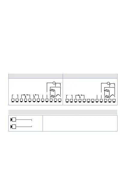
6.1 Wiring diagram
ATR144-ABC ATR144-ABC-T
+V
8 9
10 11 12
1 2 3 4
5
6 7
5A 23 0V
Resi st ive
1/8H P
Q2
Clas s 2
sour ce
24.. .2 30V
AC/D C
5A 23 0V
Resi st ive
1/8H P
Q1
DI/O1
(NPN)
PTC
NTC
-
Tc
I
V/I
+
-
PT/NI100 /1 K
Power
+V
8 9
10 11 12
1 2 3 4
5
6 7
Clas s 2
sour ce
24.. .2 30V
AC/D C
5A 23 0V
Resi st ive
1/8H P
Q1
DI/O1
(NPN)
PTC
NTC
-
Tc
I
V/I
+
-
PT/NI100 /1 K
2 wire 4/20m A
Power
-
+
RS48 5
6.1.a Power supply
1
2
Class 2 source
24...230 VAC/DC
Switching power supply 24..230 VAC/
VDC ±15% 50/60 Hz - 5 Watt/VA.
Galvanic insulation.