34 - ATR227 - Manuale d’uso
Esempi di collegamento per ingressi Volt e mA
B
2
6
+12V
30mA
4..20mA
V/A
C
PRESSURE TRANSMITTER
SENSORE DI PRESSIONE
A
1
Per segnali normalizzati in corrente 0/4..20 mA con
sensore a tre li.
Rispettare le polarità:
A= Uscita sensore
B= Massa sensore
C= Alimentazione sensore (+12Vdc / 30mA)
2
4..20mA
V/A
B
PRESSURE TRANSMITTER
SENSORE DI PRESSIONE
EXTERNAL SUPPLY
ALIMENTAZIONE
ESTERNA
A
1
Per segnali normalizzati in corrente 0/4..20 mA con
sensore ad alimentazione esterna.
Rispettare le polarità:
A= Uscita sensore
B= Massa sensore
6
+12V
30mA
4..20mA
V/A
C
PRESSURE TRANSMITTER
SENSORE DI PRESSIONE
A
1
Per segnali normalizzati in corrente 0/4..20 mA con
sensore a due li.
Rispettare le polarità:
A= Uscita sensore
C= Alimentazione sensore (+12Vdc / 30mA)
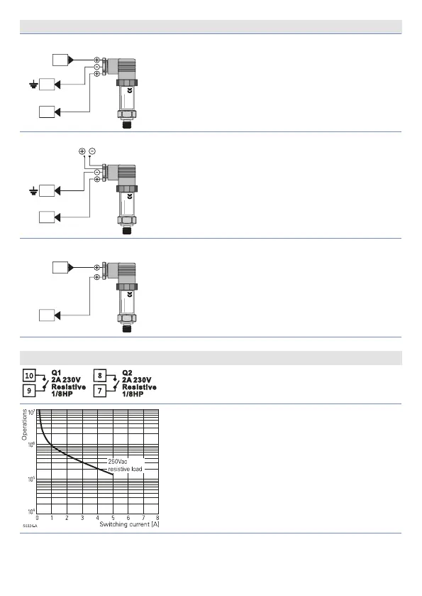
Uscita Relè Q1 - Q2
Portata contatti 5 A / 250 V~ per carichi resistivi.
NB: vedi gra co qui sotto.
Electrical endurance Q1 / Q2.
2 A, 250 Vac, carico resistivo, 10
5
operazioni.
20/2 A, 250 Vac, cosφ = 0.3, 10
5
operazioni.

 Loading...


