10 - ATR227 - User manual
SSR output
SSR command output 12 V / 30 mA.
Digital Input
PNP digital input.
Digital input according to parameter
dGti
.
To activate the digital input, shortcircuit pins 4 and 6.
6 Display and Keys Functions
A1
C2
C1
A2
1
3
4
8
9
2
5
6
7
10
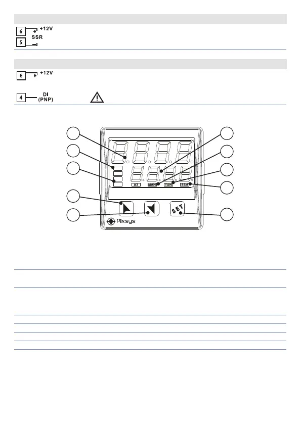
6.1 Numeric Indicators (Display)
1
1234
Normally displays the process. During conguration phase, it
displays the parameter being entered.
2
1234
Normally displays the setpoint. During conguration phase, it
displays the parameter value being entered.
6.2 Meaning of Status Lights (Led)
3 C1 ON when the output command is on.
4 A1 A2 ON when the corresponding alarm is active.
5 MAN ON when the “Manual” function is on.
6 TUN ON when the controller is running an “Autotuning” cycle.
7 REM ON when the controller communicates via serial port (USB).

 Loading...


