8 - ATR227 - User manual
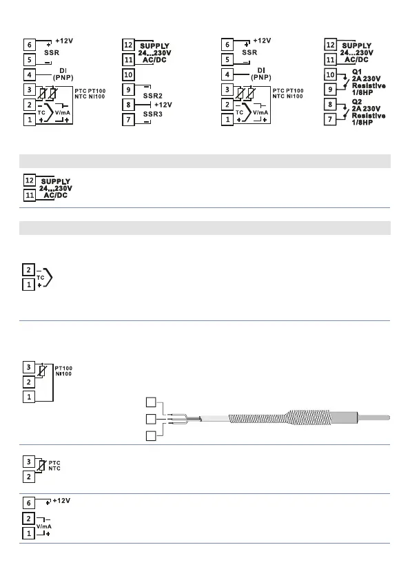
5.1 Wiring diagram
ATR227-10ABC ATR227-12ABC
Power Supply
Switching power supply with extended range 24..230 Vac/dc
±15% 50/60 Hz – 5,5 VA (galvanically insulated).
AN1 Analogue Input
For thermocouples K, S, R, J, T, E, N, B.
• Complywithpolarity
• Forpossibleextensions,usecompensatedcable
and terminals suitable for the thermocouples
used(compensated)
• Whenshieldedcableisused,itshouldbegroundedatone
side only
For thermoresistances PT100, Ni100.
• Forthethree-wireconnectionusewireswiththesame
section
• Forthetwo-wireconnectionshort-circuitterminals1and3.
• Whenshieldedcableisused,itshouldbegroundedatone
side only
RED
ROSSO
RED
ROSSO
WHITE
BIANCO
3
2
1
For thermoresistances NTC, PTC, PT500, PT1000 and linear
potentiometers
When shielded cable is used, it should be grounded at one
side only to avoid ground loop currents
•For linear signals in Volt and mA.
•Complywithpolarity.
• Whenshieldedcableisused,itshouldbegroundedatone
side only to avoid ground loop currents.
 Loading...


