15
The ber redundancy function is explained in Chapter 2.1.7
Redundancy Overview.
Note
If using Switch mode, the IGS-620TF can use 6 ports.
If using Redundant mode, the one of two Fiber port will
use for redundant. So the only 5 ports is using.
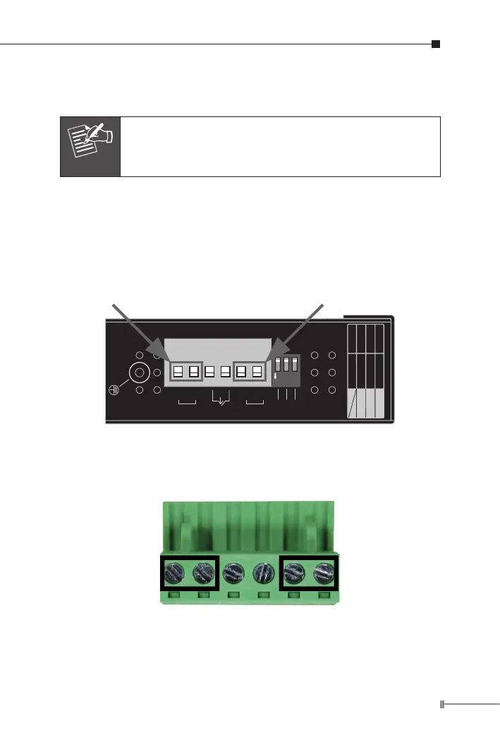
2.1.4 Wiring the Power Inputs
The 6-contact terminal block connector on the top panel of Industrial
Gigabit Ethernet Switch is used for two DC redundant power inputs.
Please follow the steps below to insert the power wire.
1. Insert positive / negative DC power wires into contacts 1 and 2 for
POWER 1, or 5 and 6 for POWER 2.
1 2 3 4 5 6
1 2 3
ON
Input DC 12~48V, AC 24V
V1-
V1+
V2-
V2+
PWR1
Port 5
Port 6
Mode
Fault
PWR2
100FX
100FX
Redundant
1000X
ON OFF
1000X
Switch
Port 5
Port 6
Fiber Mode
V1- V1+ V2- V2+
2. Tighten the wire-clamp screws for preventing the wires from loos-
ening.
1 2 3 4 5 6
Power 1 Fault Power 2
- + - +