NOTICE
Weight and balance or operating limitation changes shall be entered in the appropriate aircraft record. An alteration must be
compatible with all previous alterations to assure continued conformity with the aoolicable airworthiness requirements.
8. Description of Work Accomplished
(If more space is required, attach additional sheets. Identify with aircraft nationality and registration mark and date work completed.)
BELL 412EP S/N 36106 N412SV
PAGE 2 of 3
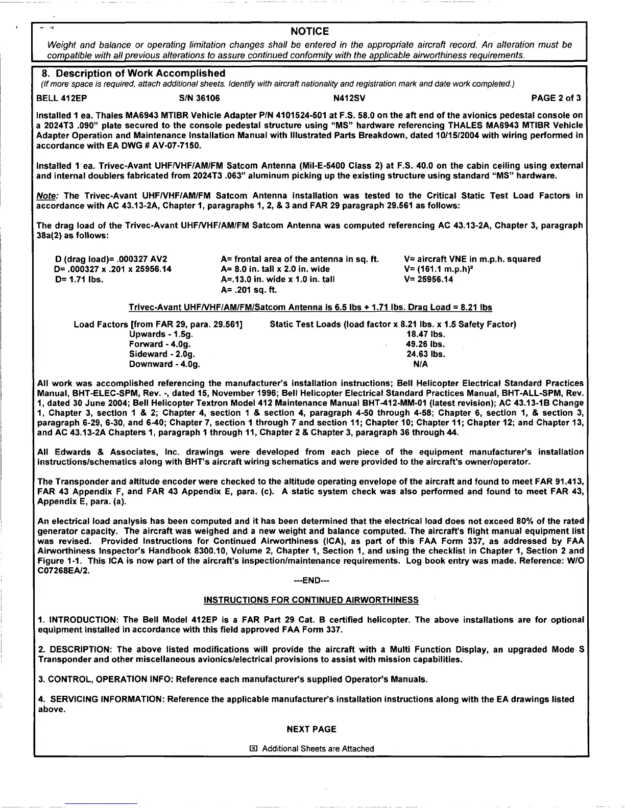
Installed 1 ea. Thales MA6943 MTIBR Vehicle Adapter P/N 4101524-501 at F.S. 58.0 on the aft end of the avionics pedestal console on
a 2024T3 .090" plate secured to the console pedestal structure using "MS" hardware referencing THALES MA6943 MTIBR Vehicle
Adapter Operation and Maintenance Installation Manual with Illustrated Parts Breakdown, dated 10/15/2004 with wiring performed in
accordance with EA DWG
# AV-07-7150.
Installed 1 ea. Trivec-Avant UHFNHF/AM/FM Satcom Antenna (Mil-E-5400 Class 2) at F.S. 40.0 on the cabin ceiling using external
and internal doublers fabricated from 2024T3 .063" aluminum picking up the existing structure using standard "MS" hardware.
Note: The Trivec-Avant UHFNHF/AM/FM Satcom Antenna installation was tested to the Critical Static Test Load Factors in
accordance with AC 43.13-2A, Chapter 1, paragraphs 1, 2, & 3 and FAR 29 paragraph 29.561 as follows:
The drag load of the Trivec-Avant UHFNHF/AM/FM Satcom Antenna was computed referencing AC 43.13-2A, Chapter 3, paragraph
38a(2) as follows:
D (drag load)= .000327 AV2
D= .000327 x .201 x 25956.14
D= 1.71 lbs.
A= frontal area of the antenna in sq. ft.
A= 8.0 in. tall x 2.0 in. wide
A=.13.0 in. wide x 1.0 in. tall
A= .201 sq. ft.
V= aircraft VNE in m.p.h. squared
V= (161.1 m.p.h)
2
V= 25956.14
Trivec-Avant UHFNHF/AM/FM/Satcom Antenna is 6.5 lbs+ 1.71 lbs. Drag Load= 8.21 lbs
Load Factors [from FAR 29, para. 29.561]
Upwards - 1.5g.
Forward - 4.0g.
Sideward - 2.0g.
Downward - 4.0g.
Static Test Loads (load factor x 8.21 lbs. x 1.5 Safety Factor)
18.47 lbs.
49.26 lbs.
24.63 lbs.
NIA
All work was accomplished referencing the manufacturer's installation instructions; Bell Helicopter Electrical Standard Practices
Manual, BHT-ELEC-SPM, Rev.-, dated 15, November 1996; Bell Helicopter Electrical Standard Practices Manual, BHT-ALL-SPM, Rev.
1, dated 30 June 2004; Bell Helicopter Textron Model 412 Maintenance Manual BHT-412-MM-01 (latest revision); AC 43.13-18 Change
1, Chapter 3, section 1 & 2; Chapter 4, section 1 & section 4, paragraph 4-50 through 4-58; Chapter 6, section 1,
& section 3,
paragraph 6-29, 6-30, and 6-40; Chapter 7, section 1 through 7 and section 11; Chapter 10; Chapter 11; Chapter 12; and Chapter 13,
and AC 43.13-2A Chapters 1, paragraph 1 through 11, Chapter 2
& Chapter 3, paragraph 36 through 44.
All Edwards
& Associates, Inc. drawings were developed from each piece of the equipment manufacturer's installation
instructions/schematics along with BHT's aircraft wiring schematics and were provided to the aircraft's owner/operator.
The Transponder and altitude encoder were checked to the altitude operating envelope of the aircraft and found to meet FAR 91.413,
FAR 43 Appendix F, and FAR 43 Appendix E, para. (c). A static system check was also performed and found to meet FAR 43,
Appendix E, para. (a).
An electrical load analysis has been computed and it has been determined that the electrical load does not exceed 80% of the rated
generator capacity. The aircraft was weighed and a new weight and balance computed. The aircraft's flight manual equipment list
was revised. Provided Instructions for Continued Airworthiness (ICA), as part of this FAA Form 337, as addressed by FAA
Airworthiness Inspector's Handbook 8300.10, Volume 2, Chapter 1, Section 1, and using the checklist in Chapter 1, Section 2 and
Figure 1-1. This ICA is now part of the aircraft's inspection/maintenance requirements. Log book entry was made. Reference: W/0
C07268EA/2.
---END---
INSTRUCTIONS FOR CONTINUED AIRWORTHINESS
1. INTRODUCTION: The Bell Model 412EP is a FAR Part 29 Cat. B certified helicopter. The above installations are for optional
equipment installed in accordance with this field approved FAA Form 337.
2. DESCRIPTION: The above listed modifications will provide the aircraft with a Multi Function Display, an upgraded Mode S
Transponder and other miscellaneous avionics/electrical provisions to assist with mission capabilities.
3. CONTROL, OPERATION INFO: Reference each manufacturer's supplied Operator's Manuals.
4. SERVICING INFORMATION: Reference the applicable manufacturer's installation instructions along with the EA drawings listed
above.
NEXT PAGE
IRl Additional Sheets are Attached
 Loading...