~PCllflEIIAMOMCS~
SkyHuntc,40~
MANL:INS:SH:X:XX
PIN 1
August 8 ,2013
Rev25
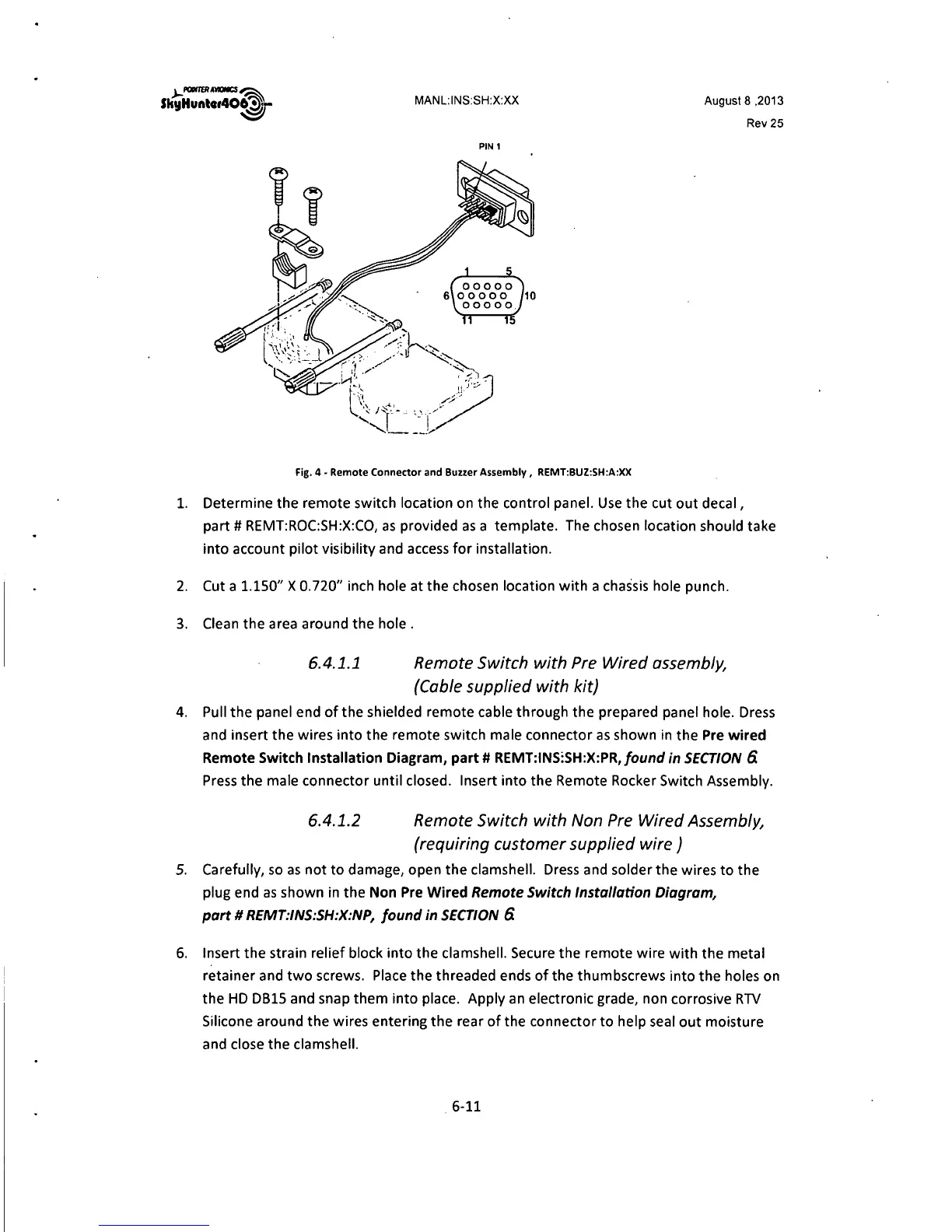
Fig. 4 - Remote Connector and Buzzer Assembly, REMT:BUZ:SH:A:XX
1. Determine the remote switch location on the control panel. Use the cut out decal,
part# REMT:ROC:SH:X:CO, as provided as a template. The chosen location should take
into account pilot visibility and access for installation.
2. Cut a
1.150" X 0.720" inch hole at the chosen location with a chassis hole punch.
3. Clean the area around the hole .
6.4.1.1 Remote Switch with Pre Wired assembly,
{Cable supplied with kit)
4. Pull the panel end of the shielded remote cable through the prepared panel hole. Dress
and insert the wires into the remote switch male connector as shown in the Pre wired
Remote Switch Installation Diagram, part# REMT:INS:SH:X:PR,/ound
in SECTION 6.
Press the male connector until closed. Insert into the Remote Rocker Switch Assembly.
6.4.1.2 Remote Switch with Non Pre Wired Assembly,
(requiring customer supplied wire)
5. Carefully, so as not to damage, open the clamshell. Dress and solder the wires to the
plug end as shown in the Non Pre Wired
Remote Switch Installation Diagram,
part# REMT:INS:SH:X:NP, found in SECTION
6.
6. Insert the strain relief block into the clamshell. Secure the remote wire with the metal
retainer and two screws. Place the threaded ends of the thumbscrews into the holes on
the HD
0815 and snap them into place. Apply an electronic grade, non corrosive RTV
Silicone around the wires entering the rear of the connector to help seal out moisture
and close the clamshell.
6-11