,_. .............................................................................................................................................................................................................................................................................. __ - \
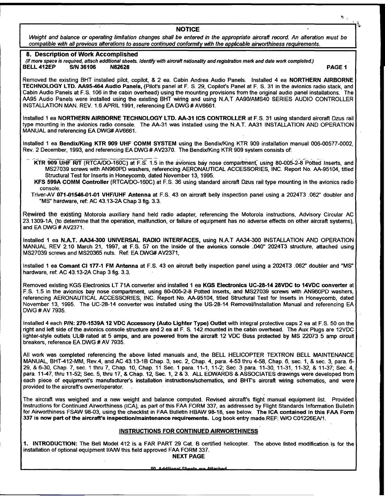
NOTICE
Weight and balance or operating limitation changes shall be entered in the appropriate aircraft record. An alteration must be
compatible with all
previous alterations to assure continued conformity with the aptJlicable airworthiness requirements.
8. Description of Work Accomplished
(If more space is required, attach additional sheets. Identify with aircraft nationality and registration mark and date work completed.)
BELL 412EP S/N 36106 N82628
PAGE1
Removed the existing BHT installed pilot, copilot, & 2 ea. Cabin Andrea Audio Panels. Installed 4 ea NORTHERN AIRBORNE
TECHNOLOGY LTD. AA95464 Audio Panels, (Pilot's panel at F. S. 29, Copilot's Panel at F. S. 31 in the avionics radio stack, and
Cabin Audio Panels at F.S. 106 in the cabin overhead) using the mounting provisions from the original audio panel installations. The
AA95 Audio Panels were installed using the existing BHT wiring and using N.A T AA90/AMS40 SERIES AUDIO CONTROLLER
INSTALLATION MAN. REV. 1.6 APRIL 1991, referencing
EA DWG#AV6661.
Installed 1 ea NORTHERN AIRBORNE TECHNOLOGY LTD. AA-31 ICS CONTROLLER at F.S. 31 using standard aircraft Dzus rail
type mounting in the avionics radio console. The AA-31 was installed using the N.A
T. AA31 INSTALLATION AND OPERATION
MANUAL and referencing EA OWG# AV6661.
Installed 1 ea Bendix/King KTR 909 UHF COMM SYSTEM using the Bendix/King KTR 909 installation manual 006-00577-0002,
Rev. 2 December, 1993, and referencing EA DWG # A V2370. The Bendix/King KTR 909 system consists
of
-- "KfR-909 UHF
R/T (RTC~160C) at F.t1.5 in the avionics bay nose compartrnen( using 80-005-2.:S-Potted Inserts, and
MS27039 screws with AN960PD washers, referencing AERONAUTICAL ACCESSORIES, INC. Report No. AA-95104, titled
Structural Test for Inserts in Honeycomb, dated November 13, 1995.
KFS 599A COMM Controller (RTCA/00-160C) at F.S. 36 using standard aircraft Dzus rail type mounting in the avionics radio
console.
Triver-AV 071-01546-01-01 VHF/UHF Antenna at F.S. 43 on aircraft belly inspection panel using a 2024T3 .062" doubler and
"MS" hardware, ret AC 43.13-2A Chap 3 fig. 3.3.
Rewired the existing Motorola auxiliary hand held radio adapter, referencing the Motorola instructions, Advisory Circular AC
23.1309-1A, (to determine that the operation, malfunction, or failure of equipment has no adverse effects on other aircraft systems),
and EADWG#AV2371.
Installed 1 ea N.A.T. AA34-300 UNIVERSAL RADIO INTERFACES, using N.A T AA34-300 INSTALLATION AND OPERATION
MANUAL REV 2.10 March 21, 1997, at F.S. 57 on the inside
of the avionics console .040" 2024T3 structure, attached using
MS27039 screws and MS20365 nuts. Ref: EA DWG#AV2371,
Installed 1 ea Comant Cl 177-1 FM Antenna at F.S. 43 on aircraft belly inspection panel using a 2024T3
.062'' doubler and "MS"
hardware, ref AC 43.13-2A Chap 3 fig. 3.3.
Removed existing KGS Electronics LT 71A converter
and installed 1 ea KGS Electronics UC-28-14 28VDC to 14VDC converter at
F.S. 1.5 in the avionics bay nose compartment, using
80-0~2-8 Potted Inserts, and MS27039 screws with AN960PD washers,
referencing AERONAUTICAL ACCESSORIES, INC. Report No. AA-95104, titled Structural Test for Inserts in Honeycomb, dated
November 13, 1995. The UC-28-14 converter was installed using the US-28-14 Removal/Installation Manual and referencing EA
DWG #AV 7935.
Installed 4 each P/N: 270-1539A 12 VDC Accessory (Auto Lighter
Type) Outlet with integral protective caps 2 ea at F.S. 50 on the
right and left side of the avionics console structure and 2 ea at F. S. 142 mounted in the cabin overhead. The Aux Plugs are 12VDC
lighter-style outlets UL® rated at 5 amps, and are powered from the aircraft 12 VDC
·Buss protected by MS 22073 5 amp circuit
breakers, reference EA DWG # AV 7935.
All work was completed referencing the above listed manuals and, the BELL HELICOPTER TEXTRON BELL MAINTENANCE
MANUAL, BHT-412-MM, Rev.4, and AC 43.13-18 Chap. 3, sec. 2, Chap. 4, para. 4-53 thru 4-58, Chap. 6, sec. 1,
& sec. 3, para. 6-
29,
& 6-30, Chap. 7, sec. 1 thru 7, Chap. 10, Chap. 11 Sec. 1 para. 11-1, 11-2; Sec. 3 para. 11-30, 11-31, 11-32, & 11-37; Sec. 4,
para. 11-47, thru
11-52; Sec. 5, thru 17, & Chap. 12, Sec. 1, 2 & 3. ALL EDWARDS & ASSOCIATES drawings were developed from
each piece of equipment's manufacturer's installation instructions/schematics, and
BHrs aircraft wiring schematics, and were
provided to the aircraft's owner/operator.
The aircraft was weighed and a new weight and balance computed. Revised aircraft's flight manual equipment list Provided
Instructions for Continued Airworthiness (ICA), as part of this FAA FORM 337, as addressed by Flight Standards Information Bulletin
for Airworthiness FSAW 98-03, using the checklist in FAA Bulletin HBAW 98-18, see below. The ICA contained in this FAA Form
337 is now part of the aircraft's inspection/maintenance requirements. Log book entry made. REF: W/0 C01226EA/1.
INSTRUCTIONS FOR CONTINUED AIRWORTHINESS
1. INTRODUCTION: The Bell Model 412 is a FAR PART 29 Cat. B certified helicopter. The above listed modification
i~ for the
installation of optional equipment 1/ANV this field approved FAA FORM 337.
NEXT PAGE
l"C"I A "" """L a
 Loading...