18 19
EN – Installation and operation guide SIMPLE MOVE 102
EN – Installation and operation guide SIMPLE MOVE 102
EN
EN
1 ASSEMBLY
1.1 Screw assembly
1.2 Fixing the Drive
▶
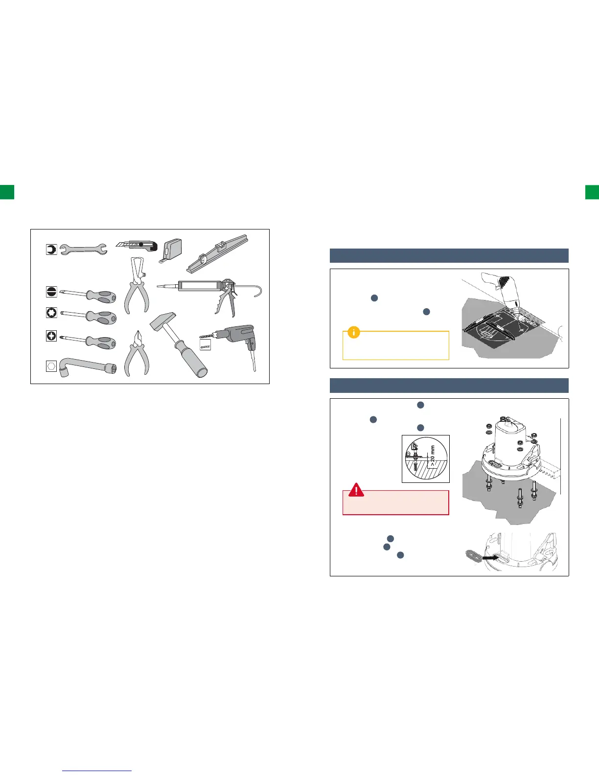
Tools required for assembly (not provided)
17
12
3,5
PZ2
T25
10
▶
The sequence of stages
• Screw assembly
• Fixing the Drive
• Toothed bar assembly
• Mechanical adjustment
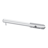
1. Place the assembly template on the ground
(the template is printed on cardboard) and drill
holes using a drill (Ø 12 mm) suitable for the
ground type.
r
2. Insert the pins (12x60 S12). Tighten
the double-thread screws (M10x15).
p
1. Screw in 4 nuts (M10, galvanized
n
)
and put 4 washers (fl at, Ø10 5x22x2,
galvanized).
o
2. Remove the cover from the drive.
a
3. Place the drive onto
the screws: the fl ange
(drive basis) must be at
a maximum height of 25
mm above the ground. The
recommended distance is
between 20 and 25 mm.
4. Aſt er the drive is set at the correct height from
the ground, attach it using washers (fl at, Ø10
5x22x2, galvanized)
o
and 4 nuts
(M10, galvanized).
n
5. Insert the cable grommet
h
that has been drilled
through in the hole provided for the supply cable.
Apply a small amount of grease to the
screws before screwing them into the pins.
Use a spirit level to check if the drive is
positioned correctly.