16 17
EN – Installation and operation guide SIMPLE MOVE 102
EN – Installation and operation guide SIMPLE MOVE 102
EN
EN
▶
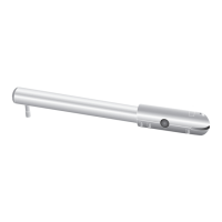
Concrete foundations
▶
Vertical setting
▶
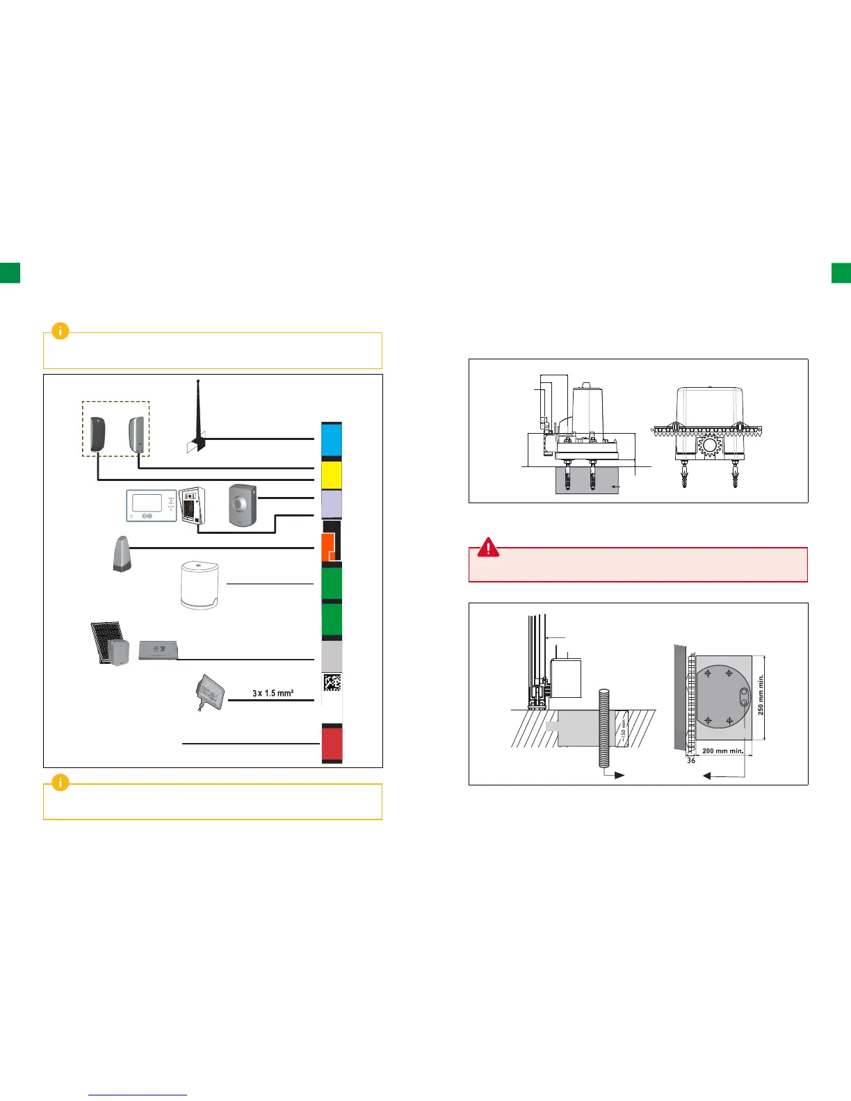
Required cables
Gate
Foundation
Foundation
Laying of cables
Toothed bar
The concrete foundations on which the drive will be installed must comply with the dimensions
indicated in the diagrams below.
The wiring details are provided in the “ACCESSORIES WIRING” section on pages from 21 to 32.
To connect several accessories to the START terminal, a cable with a 0.3 mm² cross section may be
used (example: telephone cable) instead of a cable with a cross section of 0.75 mm².
A
N
T
ANT
BUSBUS
11
33
22
44
55
66
S
T
ART
ART
M1M1
M
2
M2
1111
13131010
1212
BA
TT
BA
TT
++
--
LIG
HT
LIGHT
230V230V
1515
1717
1414
1616
77
-
F
LA
S
H
88
99
24V
+
LL
NN
TX
RX
2 x 0.75 mm²
2 x 0.75 mm²
2 x 0.75 mm²
2 x 0.75 mm²
2 x 0.75 mm²
Coaxial cable
maks. 500 W
230V power supply
3 x 1,5 mm² or 3 x 2,5 mm²
for outdoor use
(type H07RN-F mini)
The drive unit should be located slightly above the ground (more than 20 mm).
Choose a suitable position for the toothed bar. If necessary, create a concrete overlay. It is necessary to take
into account the position of the gate carriages.